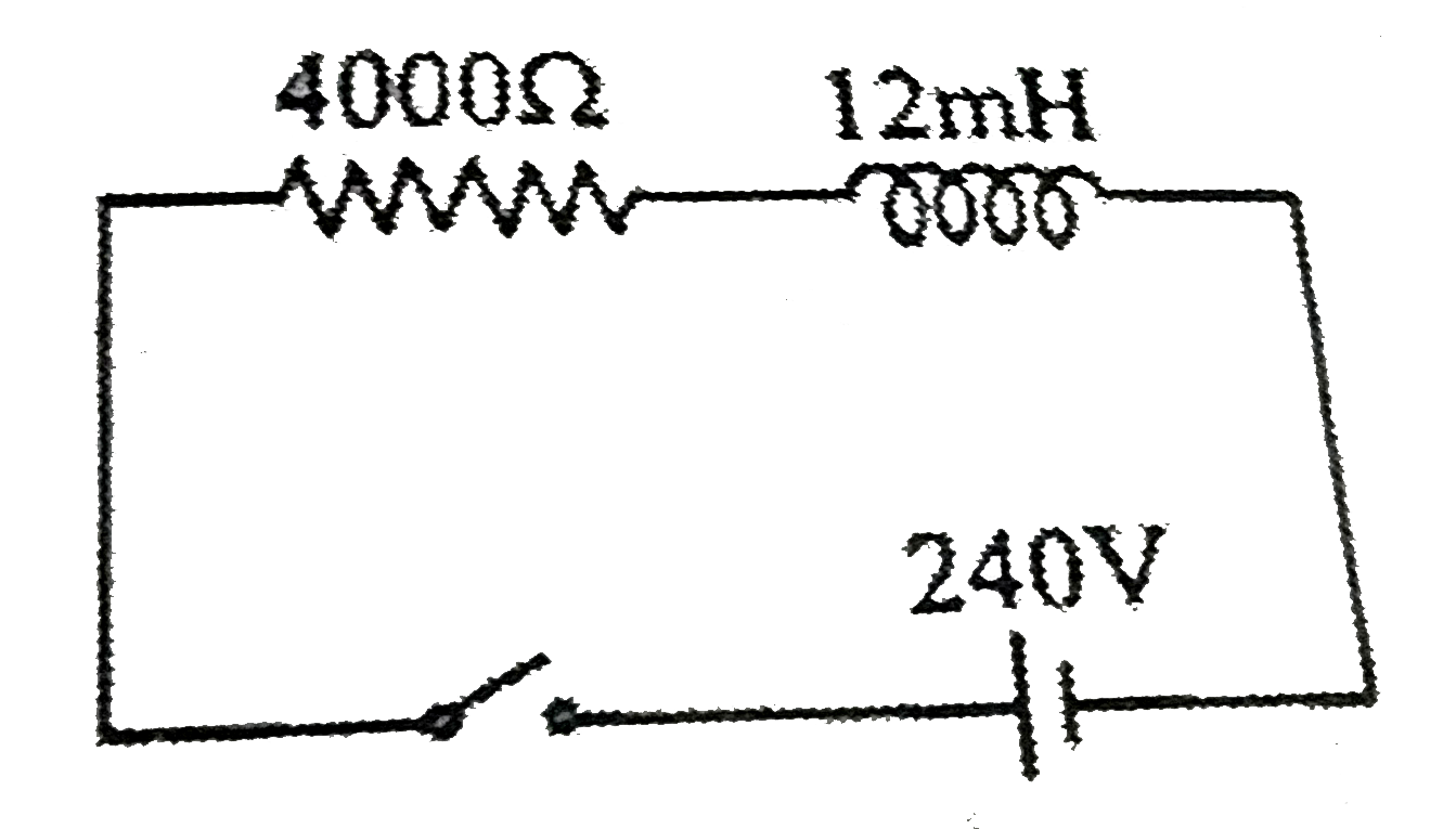
In the inductive circuit given in the figure, the current rises after the switch is closed. At instant when the current is 15 mA, then potential difference across the inductor will be-
zero
240 V
180 V
60 V
The correct Answer is:C
At any instant
VR+VL=240
iR+VL=240
VL=240−iR
=240−15×10−3×400=180V
Topper's Solved these Questions
Similar Questions
Knowledge Check
In the circuit shown, rms circuit is 11 A . The potential difference across the inductor is
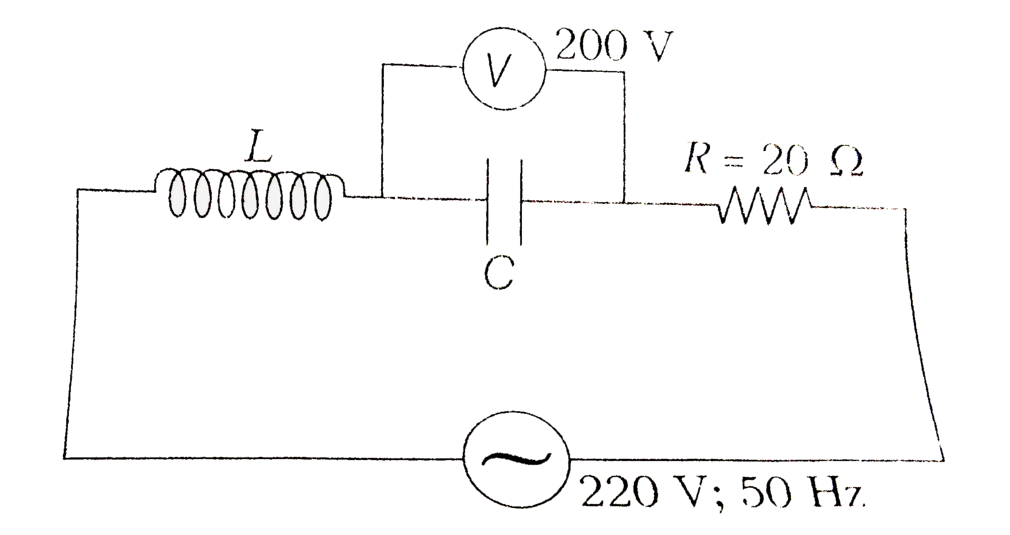 A220 VB0 VC300 VD200 V
In the given circuit, with steady current, the potential difference across the capacitor is
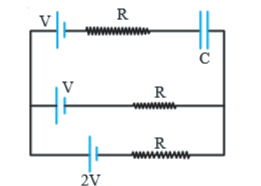 AVBV/2C2V/3DNone of these
In which of the following circuits is the current maximum just after the switch S is closed?
 A(i)B(ii)C(iii)DBoth(ii)and(iii)
In the circuit diagram the current through the battery immediately after the switch S is closed is
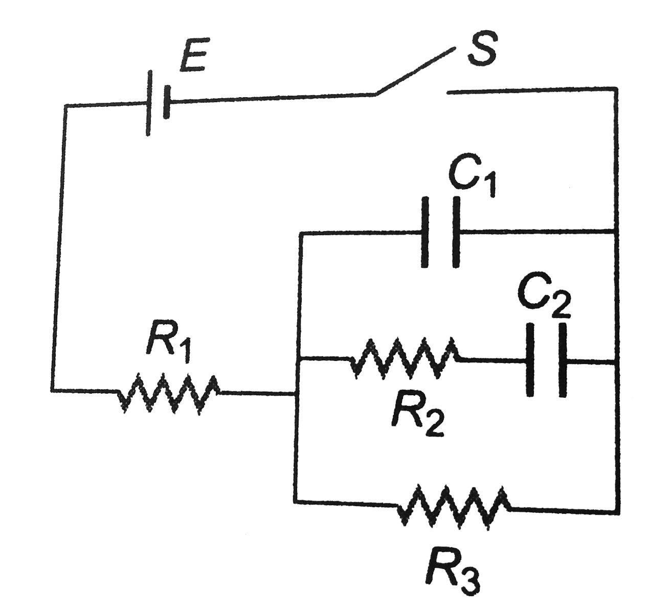
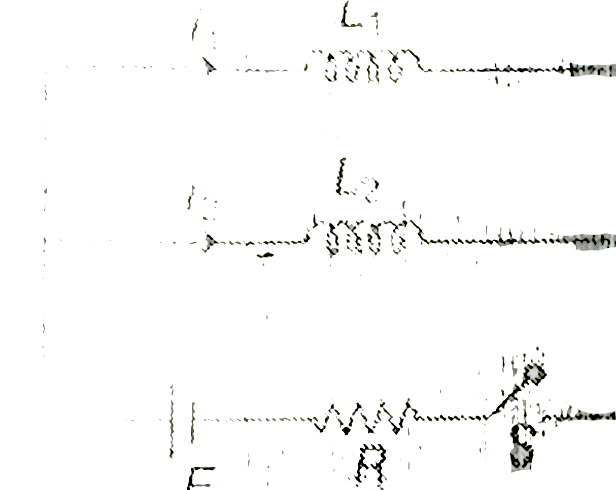
View SolutionIn the circuit shown in the figure The steady state currents i1andi2 in the coils after the switch S is closed are
View SolutionA resistor, capacitor, switch, and ideal battery are in series. Originally the capacitor is uncharged. The switch is then closed, allowing current of flow
While the current is flowing, the potential difference across the resistor is
View SolutionIn the circuit as shown in figure the switch is closed at t=0.
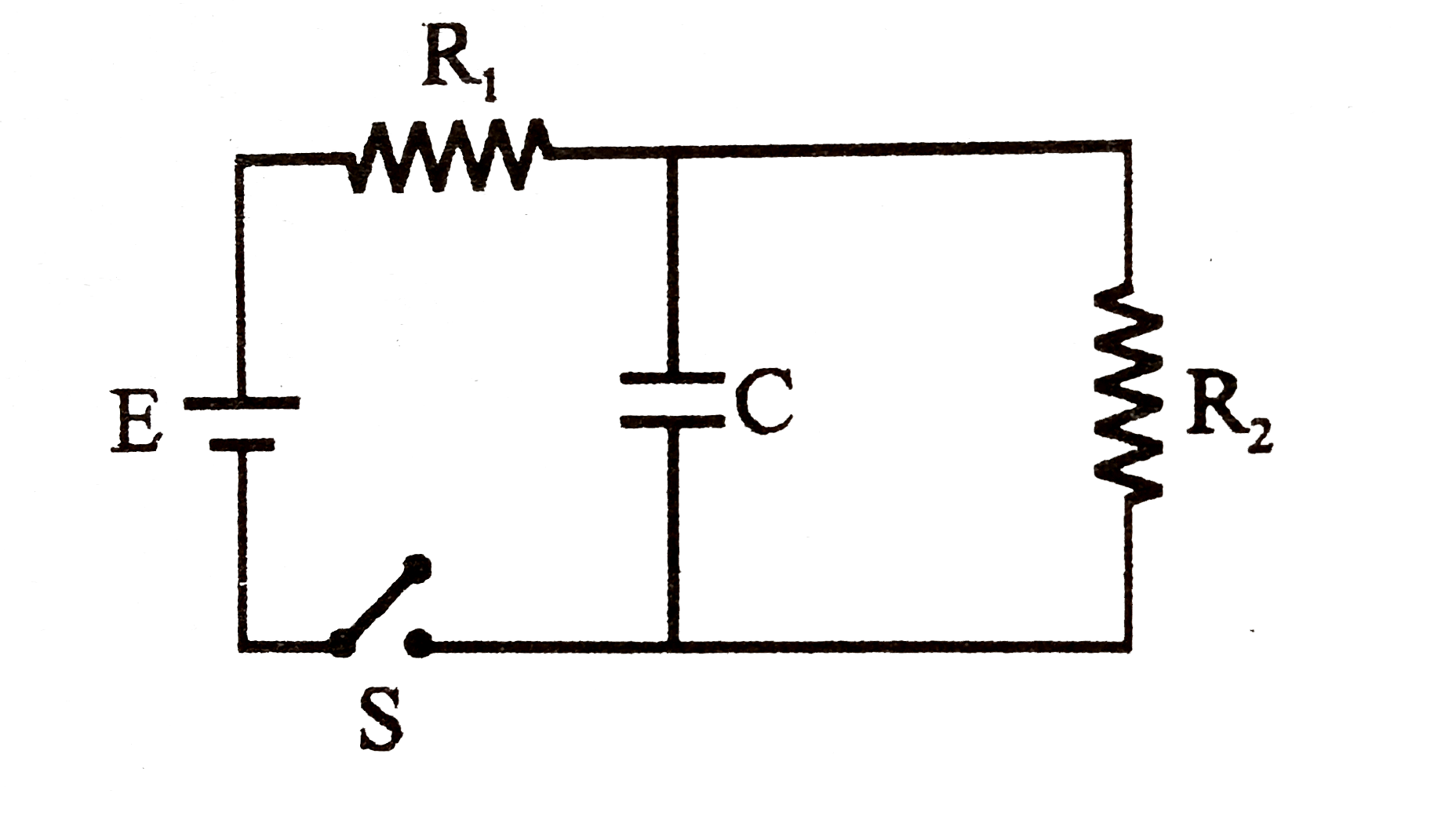
At the instant of closing the switch
View SolutionA resistor, capacitor, switch, and ideal battery are in series. Originally the capacitor is uncharged. The switch is then closed, allowing current of flow
While the current is flowing, the potential difference across the capacitor is
View Solution
