In the circuit shown in the figure (A), R3 is a variable resistance
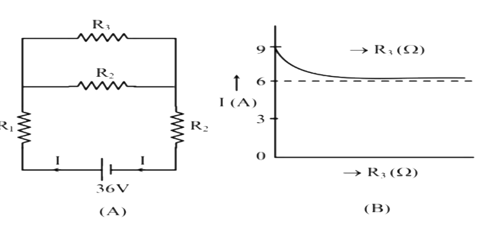
As the value R3 is changed, current I though the cell varies as shown. Obvioulsy, the variation is asymptotic, i.e. I→6A as R3→∞. Resistance R1andR2 are, respectively
The correct Answer is:4
Step by step video & image solution for In the circuit shown in the figure (A), R_(3) is a variable resistance As the value R_(3) is changed, current I though the cell varies as shown. Obvioulsy, the variation is asymptotic, i.e. Irarr6A as R_(3)rarroo. Resistance R_(1) and R_(2) are, respectively by Physics experts to help you in doubts & scoring excellent marks in Class 12 exams.
Updated on:21/07/2023Topper's Solved these Questions
Similar Questions
Knowledge Check
In the circuit shown in figure resistance of each wire is r. Net resistance across
 Aa and b is 1325rBb and c is 1950rCd and e is 725rDf and g is 1150r
In the circuit shown in the given figure, the resistances R1andR2 are respectively
 A14Ωand40ΩB40Ωand44ΩC40Ωand30ΩD14Ωand30Ω
In the circuit shown in the figure, the value of maximum rate of heat production in resistance R is
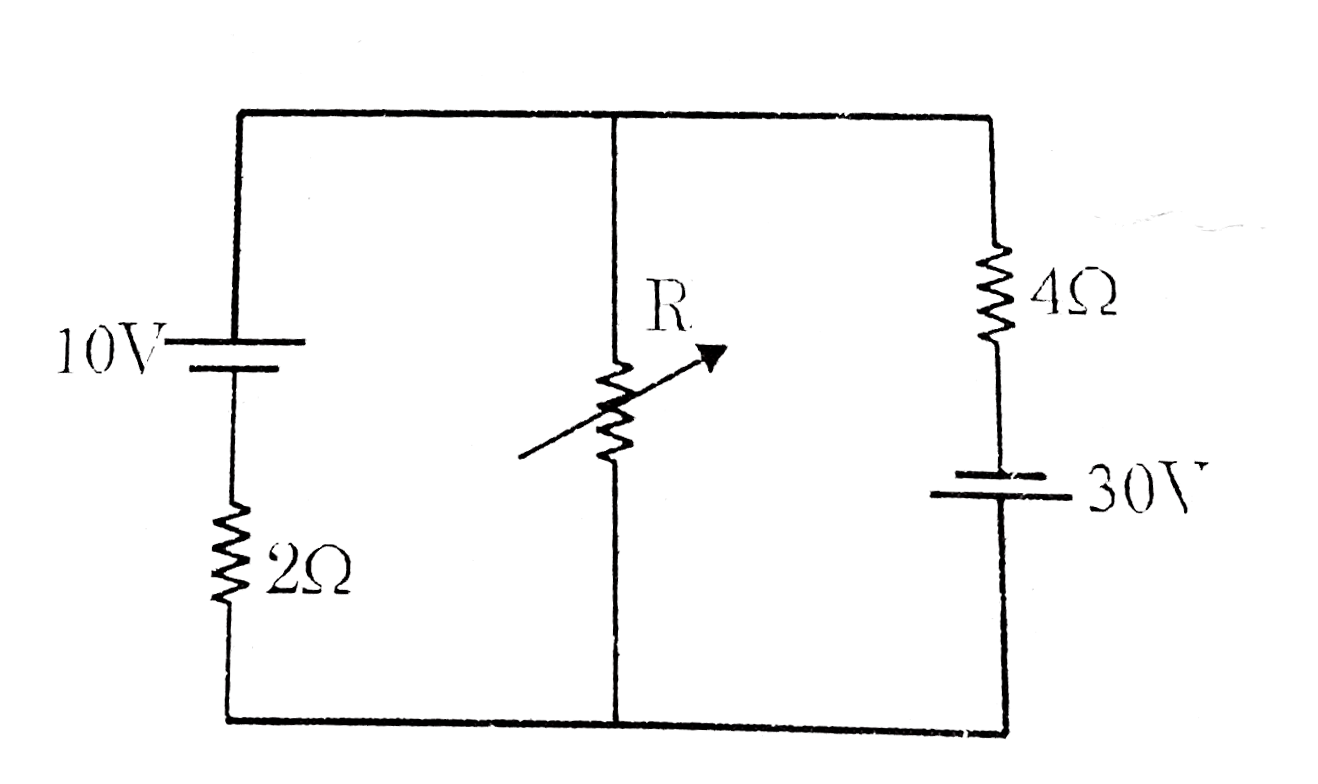 A2512WB3812WC3512WDNone
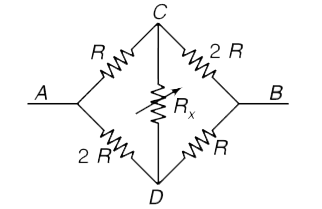
In the circuit shown in the figure RX is a variable resistance. find the equivalent resistance (RAB) between A and B in terms of RandRX. What are the possible range of values of RAB ?
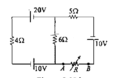
View SolutionIn the circuit shown in figure-3.196, find the value of resistance ?R at which the power transferred to this resistance will be maximum.
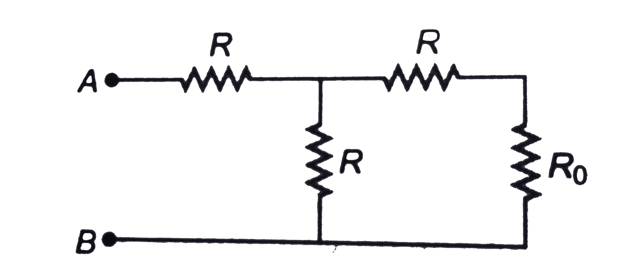
View SolutionIn the circuit shown in figure the total resistance between points A and B is R0. The value of resistance R is
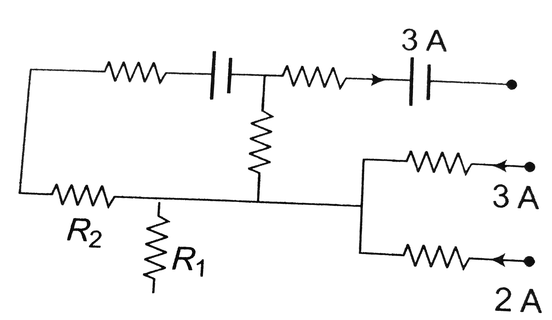
View SolutionIn the given circuit if I1 and I2 be the current in resistance R1 and R2 respectively then:
View SolutionIn the circuit shown, the galvanometer shows zero current. The value of resistance R is :
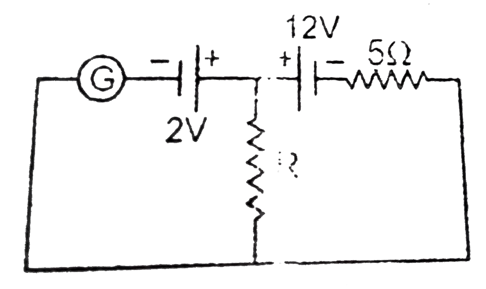
View Solution

