If all meters are ideal and the reading of the voltmeter 3 is 6 V, then power supplied by the voltage source is
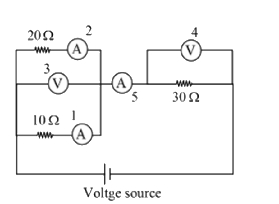
10 W
38 W
20 W
29.7 W
The correct Answer is:D
Step by step video & image solution for If all meters are ideal and the reading of the voltmeter 3 is 6 V, then power supplied by the voltage source is by Physics experts to help you in doubts & scoring excellent marks in Class 12 exams.
Updated on:21/07/2023Topper's Solved these Questions
Similar Questions
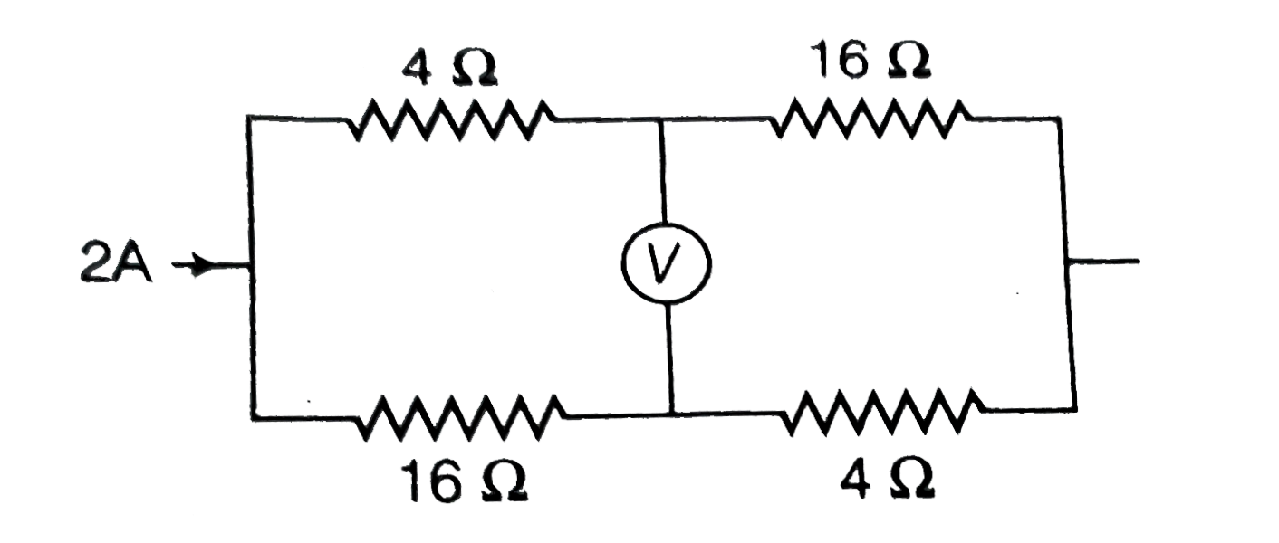
In the following circuit reading of voltmeter V is
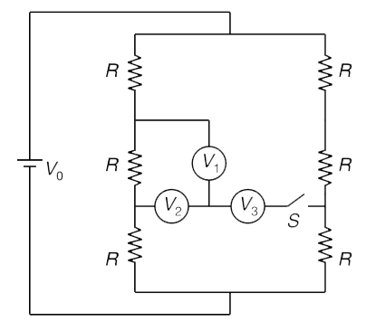
View SolutionIn the circuit shown in figure all resistances are identical (each equal to R) and the cell has an emf of V0. The three voltmeters V1,V2andV3 are identical and are nearly ideal.
(a) find the reading of the voltmeter V1 when switch ‘S’ is open.
(b) find the reading of the voltmeter V1 after the switch is closed
View Solution
Knowledge Check
Find the readings of the ammeter (A) and voltmeter (V):
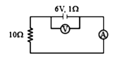 A6 A, 60 VB0.6A, 6VC6A, 6VD611A,6011V
The power dissipated in resistor R3 shown in the figure is 15 W. The reading the ammeter is 500 mA and the reading of the voltmeter is 10 V. Ammeter, voltmeter and battery are ideal.
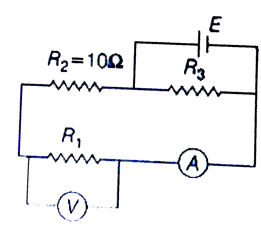
Find the resistance R3A10ΩB15ΩC20ΩD25ΩThe power dissipated in resistor R3 shown in the figure is 15 W. The reading the ammeter is 500 mA and the reading of the voltmeter is 10 V. Ammeter, voltmeter and battery are ideal.
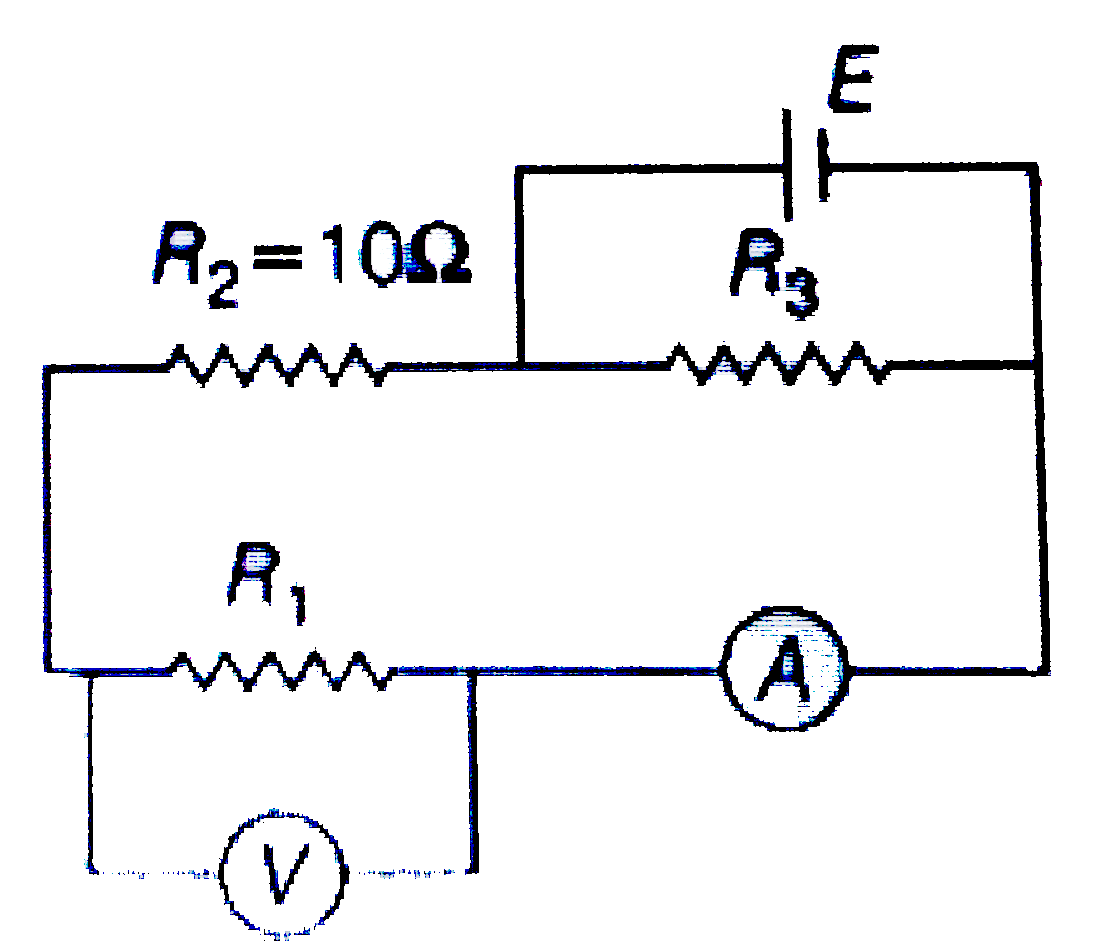
Find the resistance R1A10ΩB15ΩC20ΩD25Ω
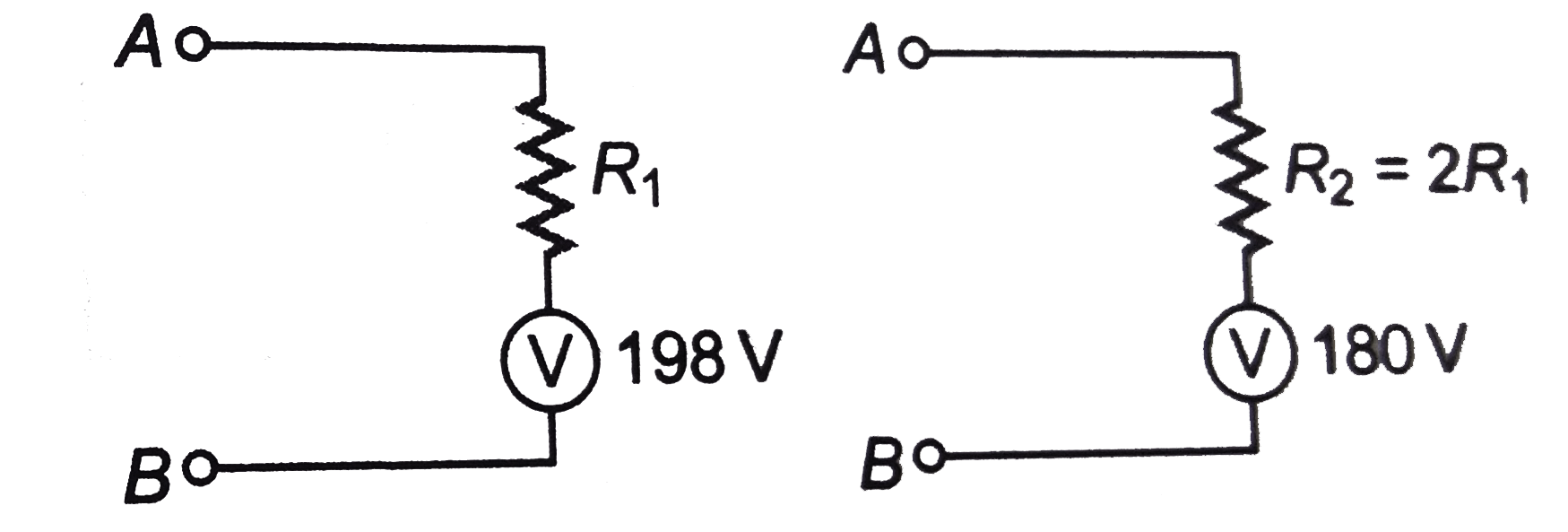
A voltmeter connected in series with a resistance R1 to a circuit indicates a voltage V1=198V. When a series resistor R2=2R1 is used, the voltmeter indicates as voltage V2=180V. If the resistance of the voltmeter is RV=900Ω, then the applied voltage ( in volt ) across A and B is
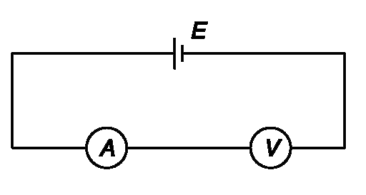
View SolutionIn the circuit shown, an ideal cell of emf E is connected in series to a non-ideal ammeter and voltmeter. Reading of the voltmeter is V0. When a resistance is added in parallel to the voltmeter its reading becomes V010 and the reading of the ammeter becomes 10 times the earlier value. find V0 in terms of E.
View SolutionThe reading of the ideal voltmeter in the adjoining diagram will be
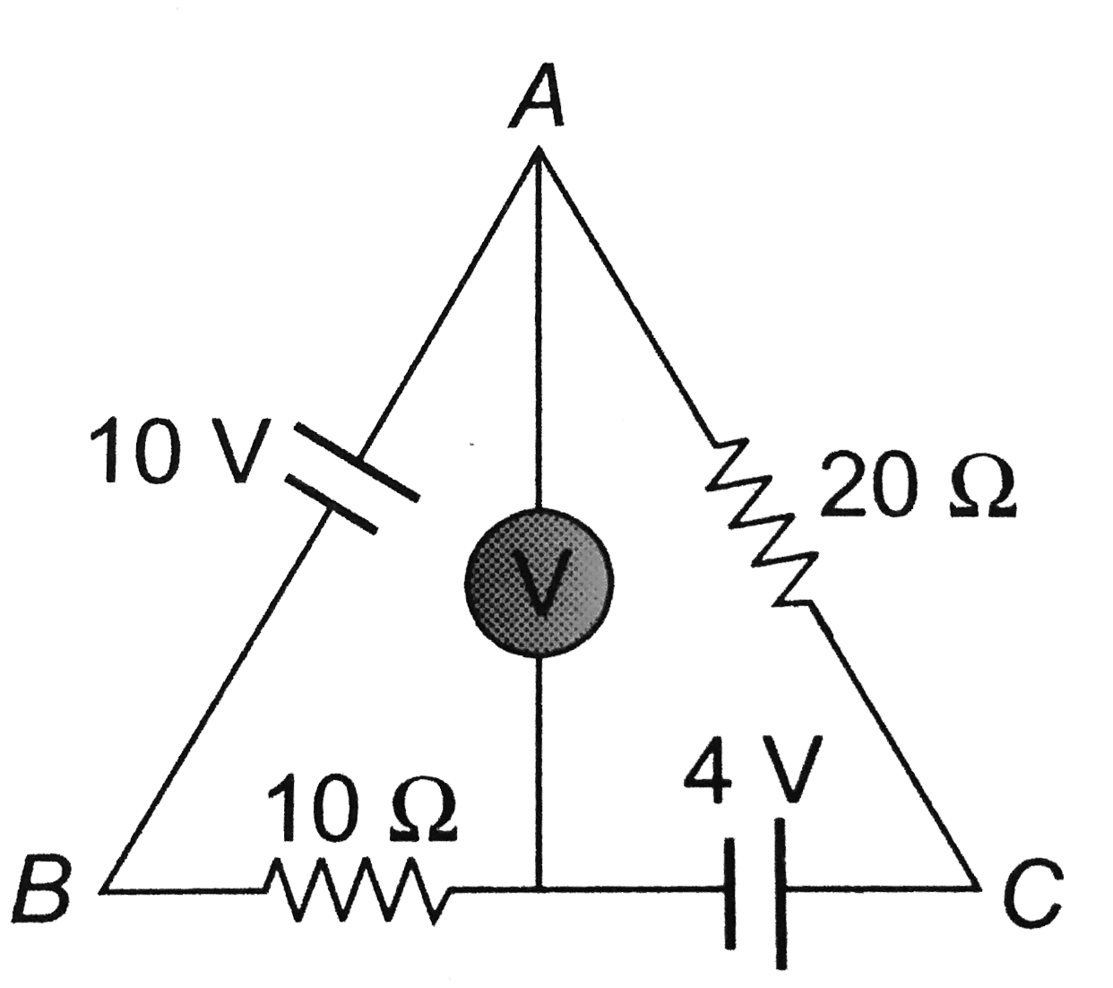
View SolutionIn the circuit figure, the voltmeter reads 30 V. The resistance of the voltmeter is
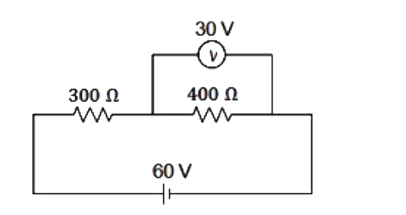
View SolutionIn the circuit shown in Fig. 6.50, an idel ammeter and an ideal voltmeter are used. Whan the key is open, the voltmeter reads 1.53V. When the key is closed, the ammeter reads 1.0A and the voltmeter reads 1.03V. The resistance R is

View Solution
