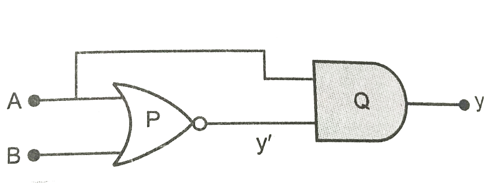
Input waveforms A and B as shown in Fig-l are applied to the combination of gates as shown in Fig-ll. Which of the waveforms shown in Fig.(i) to (iv) correctly represents the output waveform?
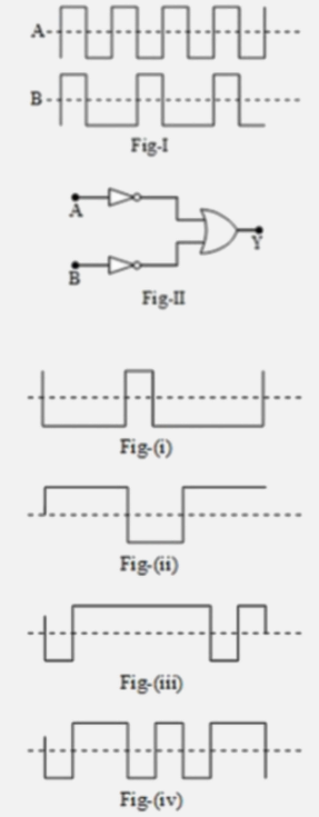
A
Fig .(i)
B
Fig .(ii)
C
Fig .(iii)
D
Fig .(iv)
Video Solution
Text Solution
The correct Answer is:C
|
Answer
Step by step video & image solution for Input waveforms A and B as shown in Fig-l are applied to the combination of gates as shown in Fig-ll. Which of the waveforms shown in Fig.(i) to (iv) correctly represents the output waveform? by Physics experts to help you in doubts & scoring excellent marks in Class 12 exams.
Updated on:21/07/2023Topper's Solved these Questions
Similar Questions
Knowledge Check
The combination of the gates shown represents :-
_E01_431_Q01.png) AAND gateBOR gateCNAND gateDNOR gate
AAND gateBOR gateCNAND gateDNOR gateIdentify the logic gate G in the combination of gates shown in fig. The truth table is shown here
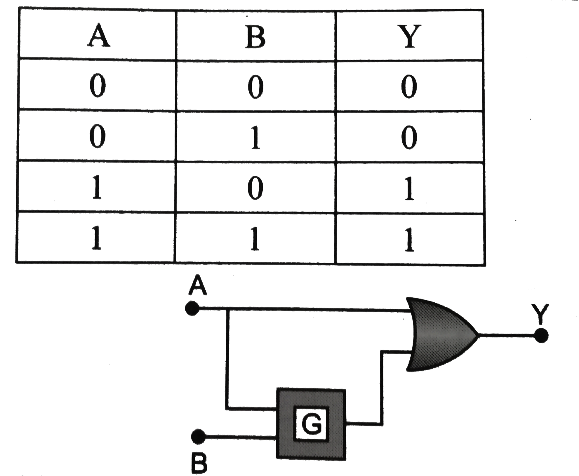 AOR gateBAND gateCNOTgateDNOR gate
There are two coils A and B as shown in Fig.
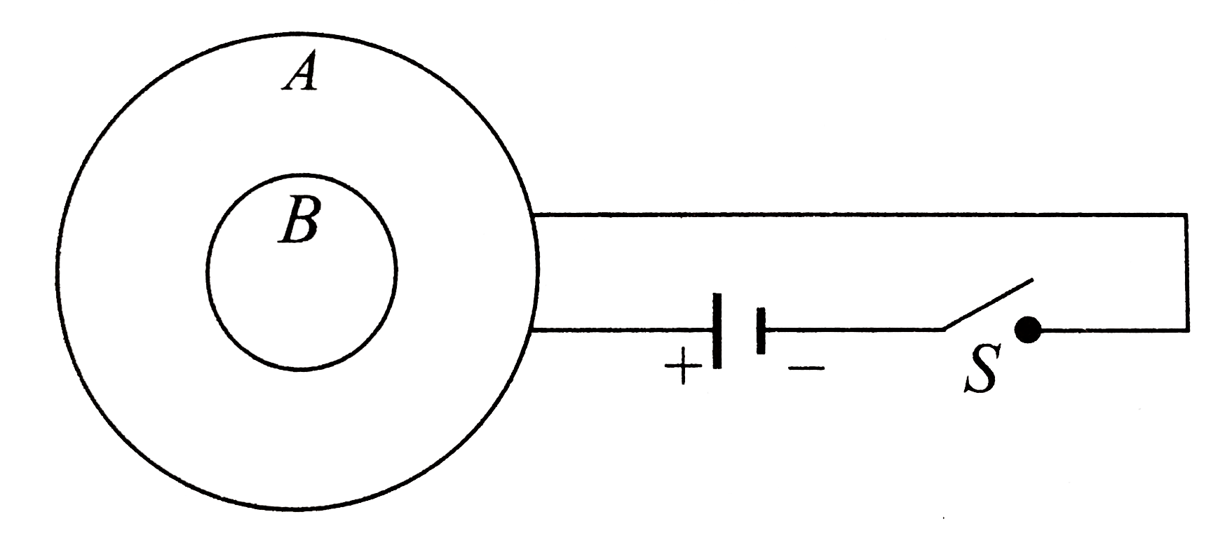 AWhen switch S is closed, the direction of the momentary current induced in coil B will be in anticlockwise directionBWhen switch S is closed, the direction of the momentary current induced in coil B will be in clockwise direction.CWhen switch S is opened, the direction of the momentary induced current in coil B will be in clockwise directionDWhen switch S is opened, the direction of the momentary induced current in coil B will be in anticlockwise direction.
The combination of the gates shown represents : -

View SolutionWrite the truth table for the combination of the gates shown in Fig. Name the gates used.
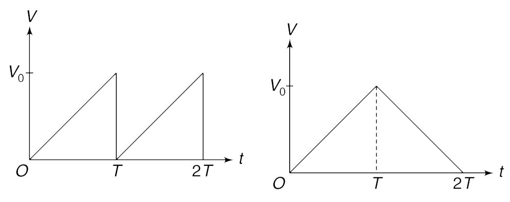
View SolutionWhich of the two waveforms shown in Figure has a higher rms value?
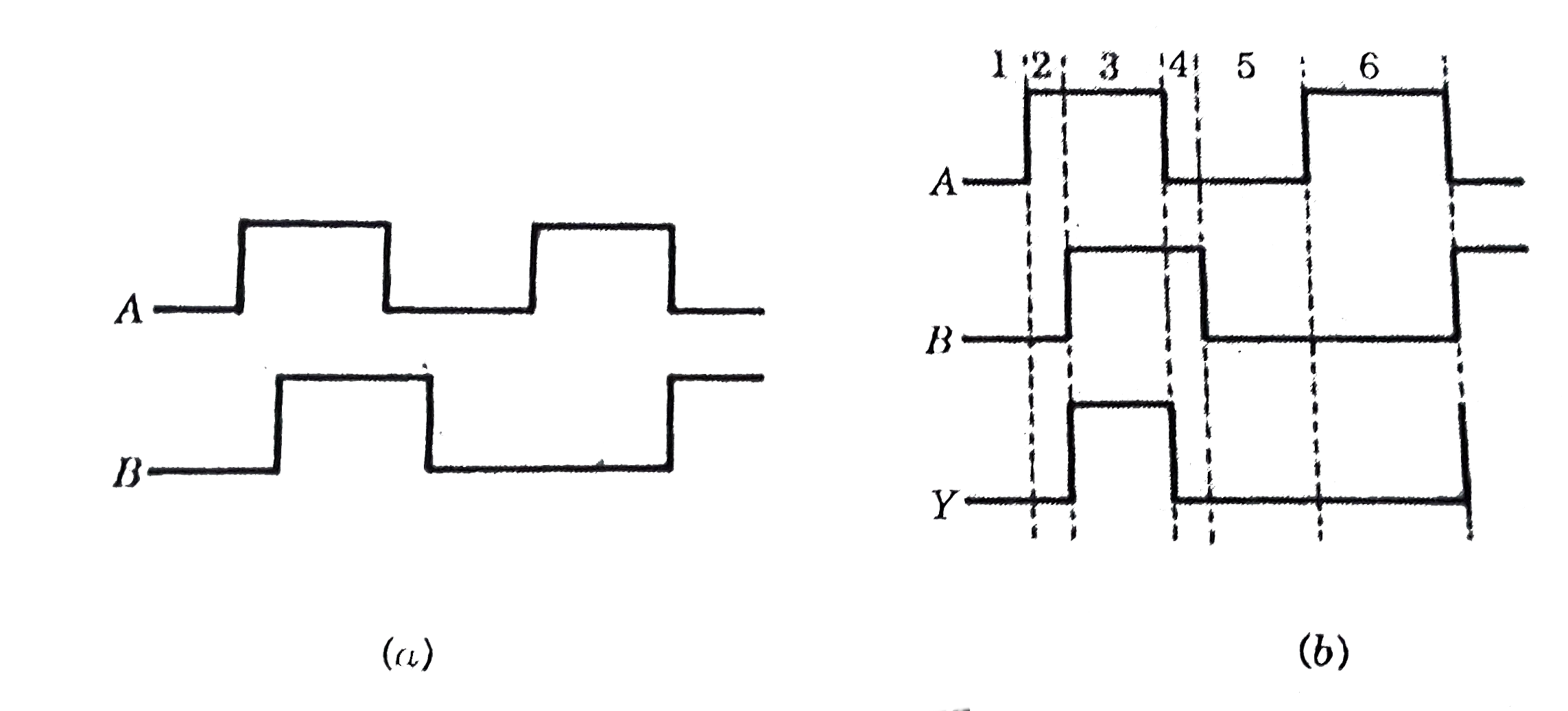
View SolutionTwo input waveforms A and B shown in fig (a) are applied to an AND gate.Write the output waveform.
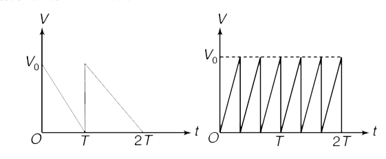
View SolutionWhich of the two waveforms shown in Figure has a higher average value?
View Solution


