The circuit as shown in the figure is equivalent to
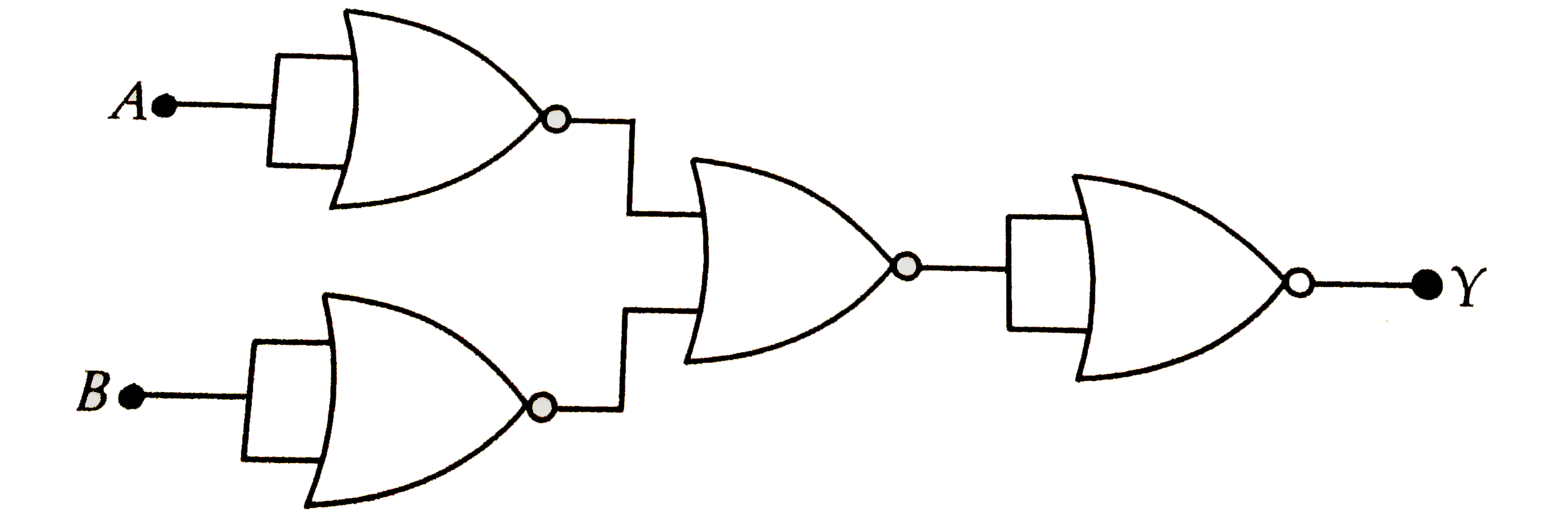
A
AND gate
B
NOT gate
C
OR gate
D
NAND gate
Video Solution
Text Solution
The correct Answer is:D
|
Answer
Step by step video, text & image solution for The circuit as shown in the figure is equivalent to by Physics experts to help you in doubts & scoring excellent marks in Class 12 exams.
Updated on:21/07/2023
Topper's Solved these Questions
- BOOK - NCERT FINGERTIPSCHAPTER - PRACTICE PAPPEREXERCISE - Practice Paper 250videos
PRACTICE PAPPER
- BOOK - NCERT FINGERTIPSCHAPTER - PRACTICE PAPPEREXERCISE - Practice Paper 350videos
PRACTICE PAPPER
- BOOK - NCERT FINGERTIPSCHAPTER - NUCLEIEXERCISE - Assertion And Reason15videos
NUCLEI
- BOOK - NCERT FINGERTIPSCHAPTER - RAY OPTICS AND OPTICAL INSTRUMENTSEXERCISE - Assertion And Reason15videos
RAY OPTICS AND OPTICAL INSTRUMENTS
Similar Questions
Knowledge Check
- Question 1 - Select One
The circuit as shown in figure is equivalent to
 ANOR gateBOR gateCAND gateDNAND gate
 - Question 2 - Select One
The circuit as shown in figure is equivalent to
 AOR gateBNOR gateCNAND gateDAND gate
 - Question 3 - Select One
The circuit shown in the figure acts as
 AOR gateBAND gateCNOT gateDNAND gate
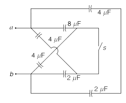
In the circuit shown in the Figure find the equivalent capacitance between points a and b when–
(a) Switch S is open.
(b) Switch S is closed.
 View Solution
In the circuit shown in the figure,
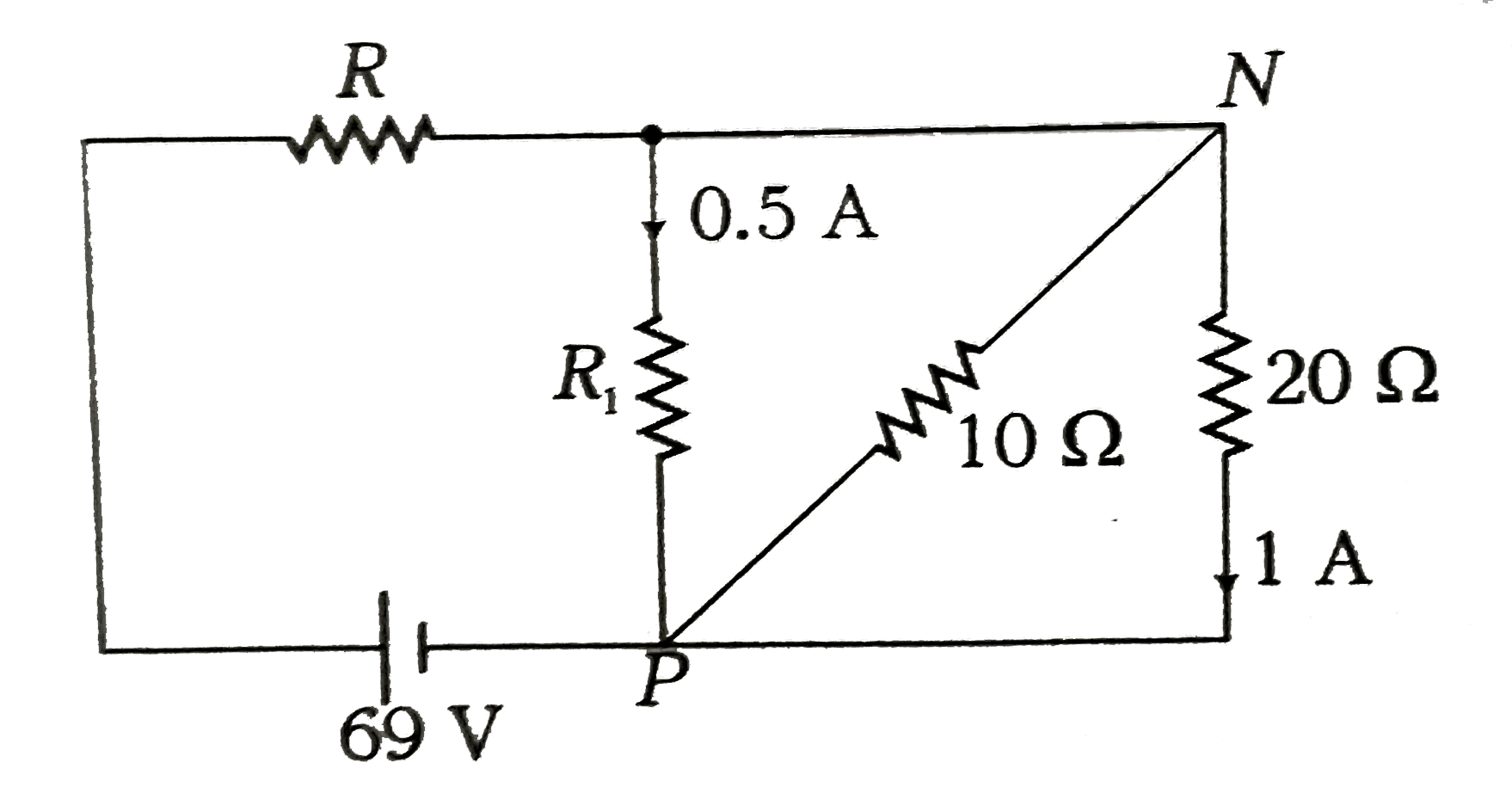 View Solution
In the circuit shown in the figure
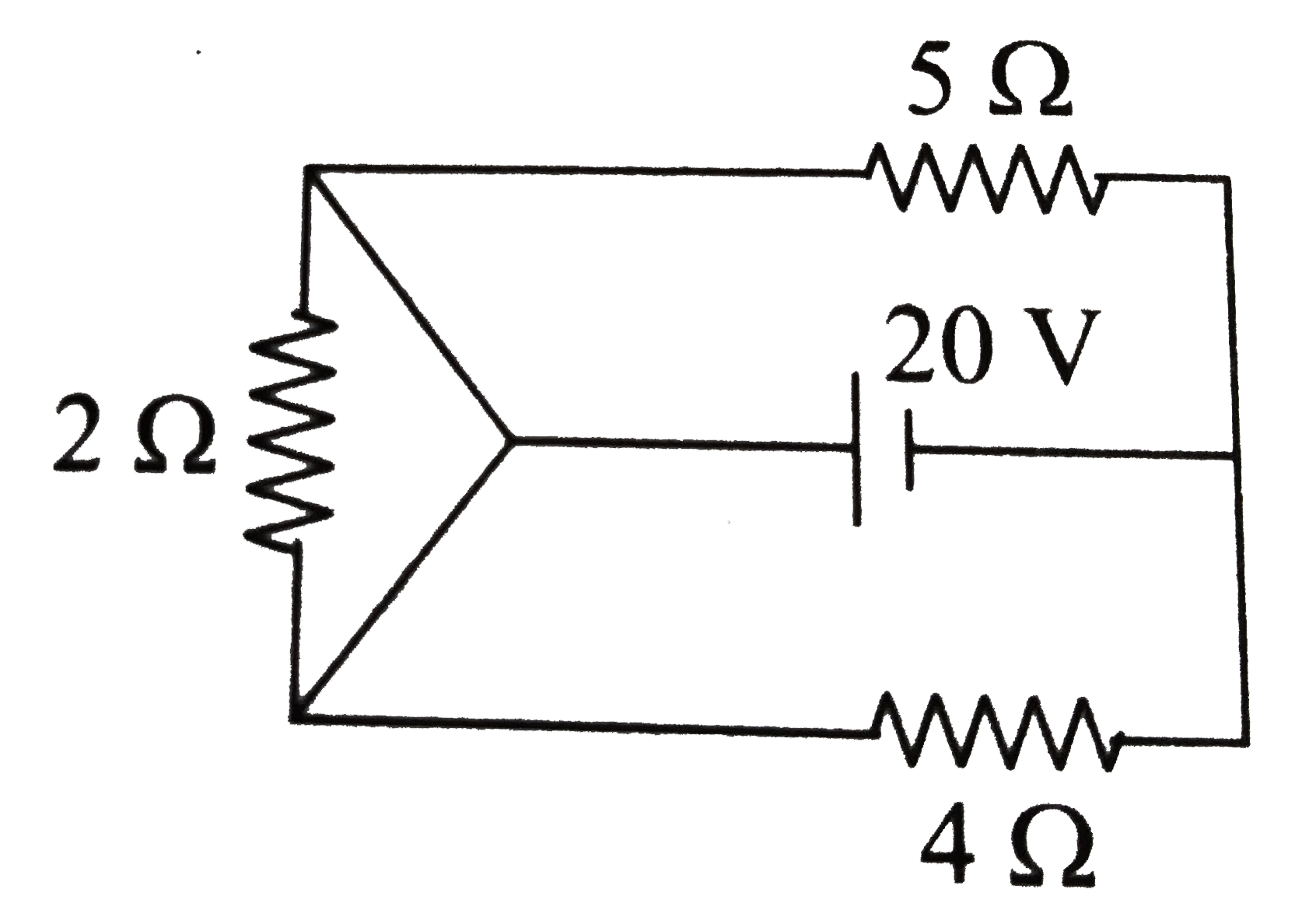 . View Solution
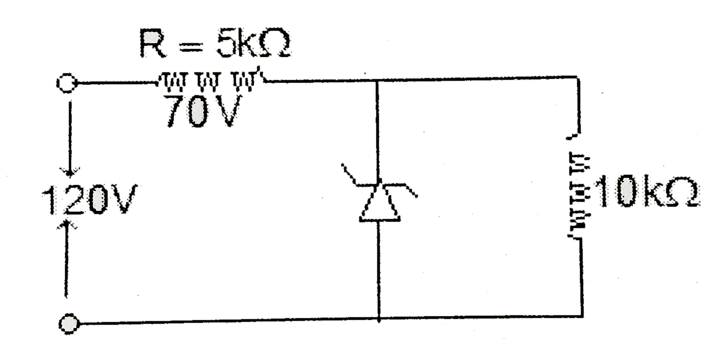
For the circuit shown in the figure:View SolutionConsider the circuit as shown in figure. The equivalent resistance between A and B is
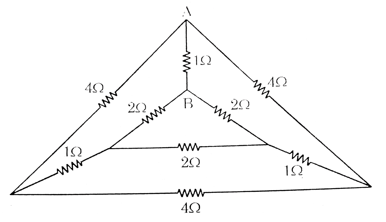 View Solution


