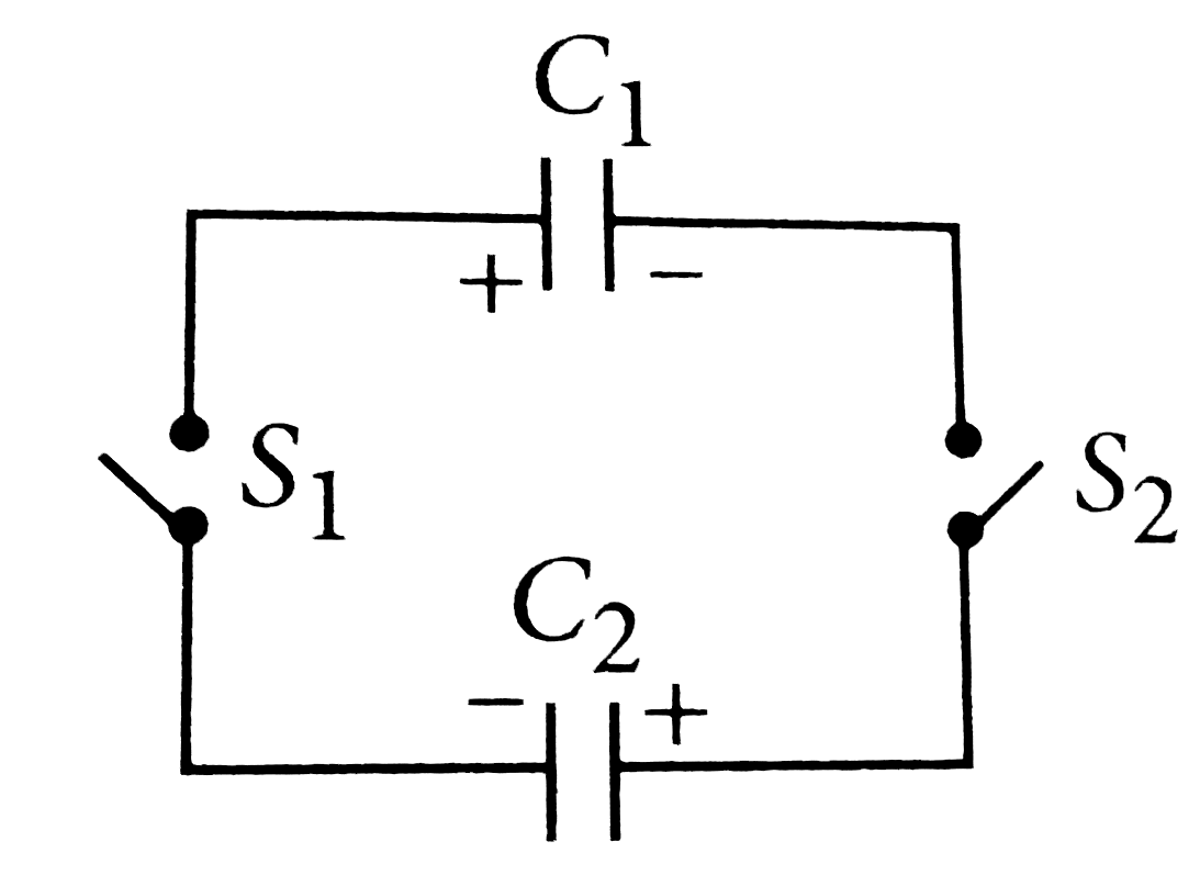
Two capacitors C1=2μF and C2=1μF are charged to same potential V=100V, but with opposite polarity as shown in the figure.
The switches S1 and S2 are closed. The ratio of final energy to the initial energy of the system is
1
12
19
14
The correct Answer is:C
Topper's Solved these Questions
- PRACTICE PAPPERBOOK - NCERT FINGERTIPSCHAPTER - PRACTICE PAPPEREXERCISE - Practice Paper 2
50 Videos
- NUCLEIBOOK - NCERT FINGERTIPSCHAPTER - NUCLEIEXERCISE - Assertion And Reason
15 Videos
- RAY OPTICS AND OPTICAL INSTRUMENTSBOOK - NCERT FINGERTIPSCHAPTER - RAY OPTICS AND OPTICAL INSTRUMENTSEXERCISE - Assertion And Reason
15 Videos
Similar Questions
Two capacitors C1=4μFandC2=2μF are charged to same potential V = 500 Volt, but with opposite polarity as shown in the figure. The switches S1andS2 are closed.

View SolutionTwo capacitors C1 and C2 are charged to same potential V, but with opposite polarity as shown in the figure. The switches S1 and S2 are then closed

View Solution
Knowledge Check
Two capacitorsC1=4μFandC2=2μF are charged to same potential V = 500 Volt, but with opposite polarity as shown in the figure. The switches S1andS2are closed.
AThe potential difference across the two capacitors are same and is given by 500/3VBThe potential difference across the two capacitors are same and is given by 1000/3VCThe ratio of final energy to initial energy of the system is 1/9DThe ratio of final energy to initial energy of the system is 4/9Two capacitors C1 and C2 are charged to same potential V, but with opposite polarity as shown in the figure. The switches S1 and S2 are then closed
 APotential difference across two capacitors are same and is given by (C1−C2)VC1+C2BPotential difference across two capacitors are same and is given by (C1+C2C1−C2)VCRatio of final energy to initial energy of the system is given by (C1−C2)2(C1+C2)2DRatio of final energy to initial energy of the system is given by (C1)2(C1+C2)2
Two capacitors C1andC2 are charged to the same potential V, but with opposite polarity as shown in the figure. The switch S1andS2 are then closed.
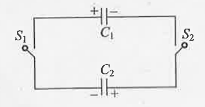 APDs across. Two capacitors are the same and is given by (C1−C2)V(C1+C2)BPDs across two capacitors are the same and is given by C1V(C1+C2)CRatio of final energy to initial energy of the system is ((C1−C2)(C1+C2))2DRatio of final energy to initial energy of the system is ((C1)(C1+C2)2)
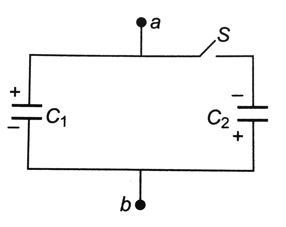
Two capacitors C1=1μF and C2=3μF each are charged to a potential difference of 100V but with opposite polarity as shown in the figure. When the switch S is closed, the new potential difference between the points a and b is
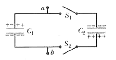
View SolutionIn fig 25-39 the capacitances are C1=1.0μFandC2=3.0μF and both capacitors are charged to a potential difference of V=200V but with opposite polarity as shown. Switches S1andS2 are now closed. (a) What is the now the potential difference between points a and b? What now is the charge on capacitor (b) 1 and (c) 2?
View SolutionTwo capacitors of capacity 6μF and 3μF are charge 100V and 50V separately and connected as shown in figure. Now all the three switches S1,S2, and S3 are closed.
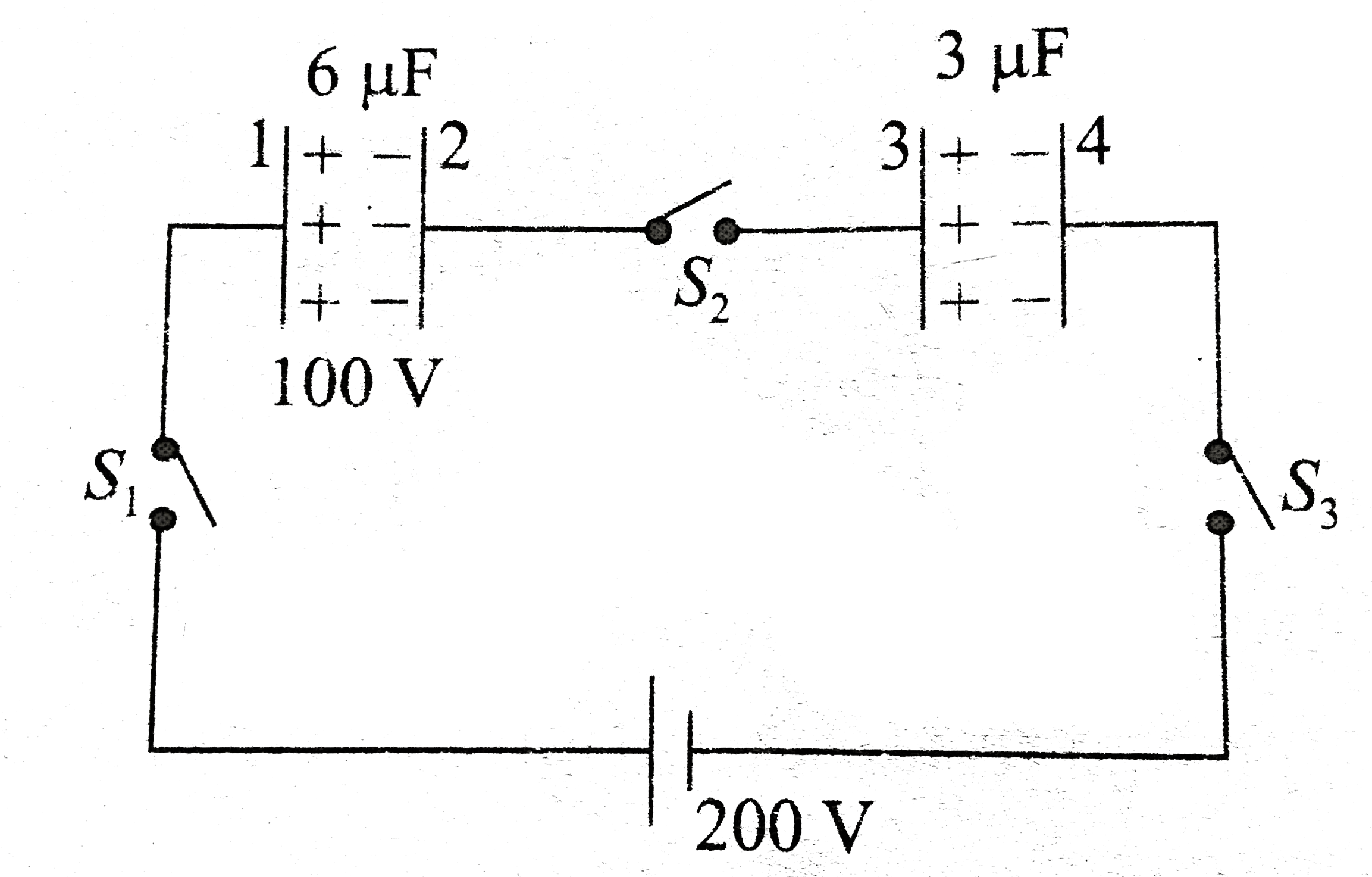
Charge on the 3μF capacitor in steady state willl be.
View SolutionTwo capacitors C1=1μF and C2=3μF each are charged to a potential difference of 100V but with opposite polarity as shown in the figure. When the switch S is closed, the new potential difference between the points a and b is

View SolutionTwo capacitors of capacity 6μF and 3 muFarechar≥100 Vand50 Vseparatelyandco∩ectedasshown∈NowallthethreeswitchesS_(1),S_(2),andS_(3) are closed.
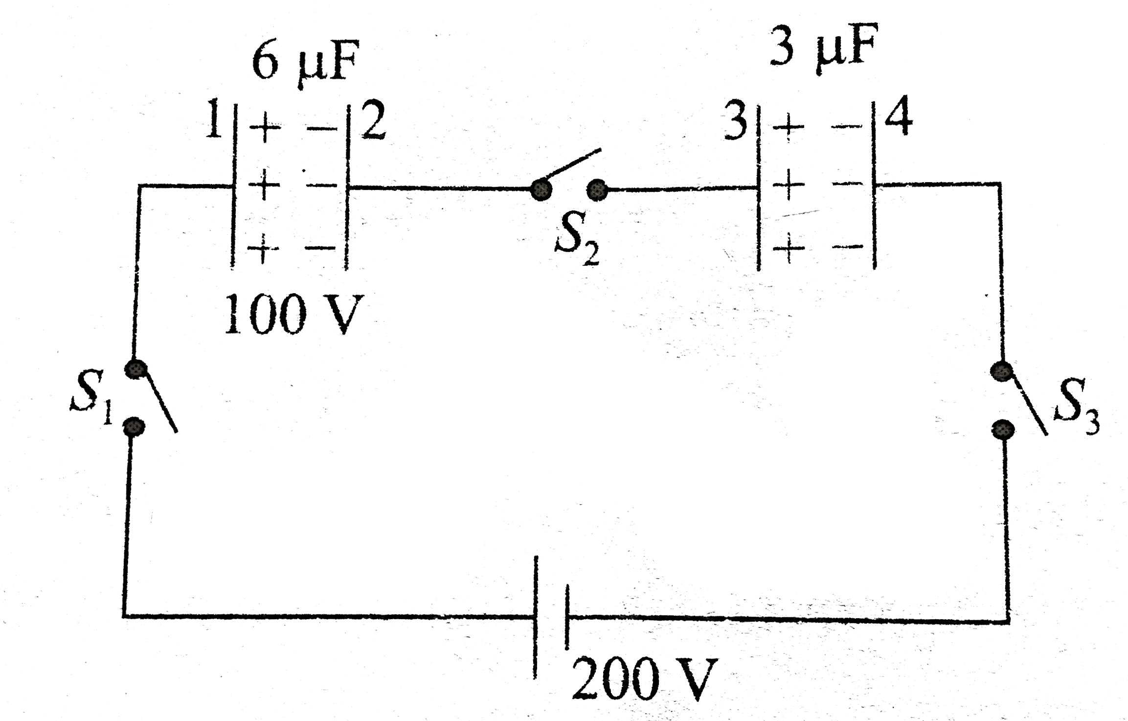
Which plates form an isolated system?
View Solution
