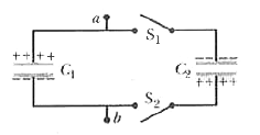
In fig 25-39 the capacitances are C1=1.0μFandC2=3.0μF and both capacitors are charged to a potential difference of V=200V but with opposite polarity as shown. Switches S1andS2 are now closed. (a) What is the now the potential difference between points a and b? What now is the charge on capacitor (b) 1 and (c) 2?

a)100Vb)1.0×10⁻⁴Cc)3.0×10⁻⁴C
Topper's Solved these Questions
- BOOK - RESNICK AND HALLIDAYCHAPTER - CAPACITANCEEXERCISE - PRACTICE QUESTIONS (SINGLE CORRECT CHOICE TYPE)23videos
CAPACITANCE
- BOOK - RESNICK AND HALLIDAYCHAPTER - CAPACITANCEEXERCISE - PRACTICE QUESTIONS (MORE THAN ONE CORRECT CHOICE TYPE)12videos
CAPACITANCE
- BOOK - RESNICK AND HALLIDAYCHAPTER - CAPACITANCEEXERCISE - CHECKPOINTS4videos
CAPACITANCE
- BOOK - RESNICK AND HALLIDAYCHAPTER - ALL ABOUT ATOMS EXERCISE - CHECKPOINT1videos
ALL ABOUT ATOMS
- BOOK - RESNICK AND HALLIDAYCHAPTER - CENTER OF MASS EXERCISE - Practice Questions (Integer )4videos
CENTER OF MASS
Similar Questions
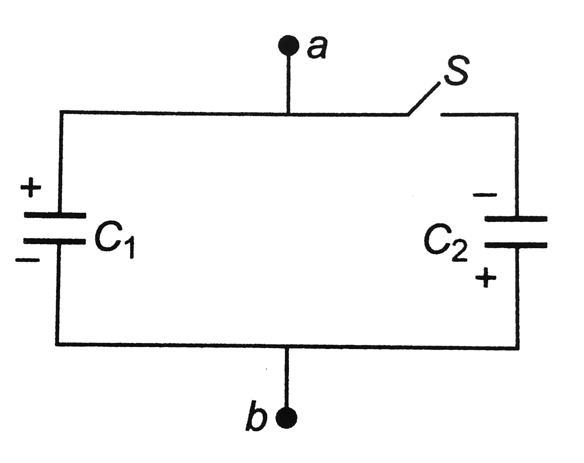
Two capacitors C1=1μF and C2=3μF each are charged to a potential difference of 100V but with opposite polarity as shown in the figure. When the switch S is closed, the new potential difference between the points a and b is
 View Solution
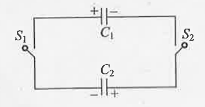
Two capacitors C1 and C2 are charged to same potential V, but with opposite polarity as shown in the figure. The switches S1 and S2 are then closed
 View Solution
Knowledge Check
- Question 1 - Select One
Two capacitors C1=1μF and C2=3μF each are charged to a potential difference of 100V but with opposite polarity as shown in the figure. When the switch S is closed, the new potential difference between the points a and b is
 A200VB100VC50VD25V
 - Question 2 - Select One or More
Two capacitors C1 and C2 are charged to same potential V, but with opposite polarity as shown in the figure. The switches S1 and S2 are then closed
 APotential difference across two capacitors are same and is given by (C1−C2)VC1+C2BPotential difference across two capacitors are same and is given by (C1+C2C1−C2)VCRatio of final energy to initial energy of the system is given by (C1−C2)2(C1+C2)2DRatio of final energy to initial energy of the system is given by (C1)2(C1+C2)2
 - Question 3 - Select One or More
Two capacitorsC1=4μFandC2=2μF are charged to same potential V = 500 Volt, but with opposite polarity as shown in the figure. The switches S1andS2are closed.
AThe potential difference across the two capacitors are same and is given by 500/3VBThe potential difference across the two capacitors are same and is given by 1000/3VCThe ratio of final energy to initial energy of the system is 1/9DThe ratio of final energy to initial energy of the system is 4/9
Two capacitors C1=4μFandC2=2μF are charged to same potential V = 500 Volt, but with opposite polarity as shown in the figure. The switches S1andS2 are closed.
 View Solution
A 100μF capacitor is charged to a potential difference of 24V. It is connected to an uncharged capacitor of capacitance 20μF What will be the new potential difference across the 100μF capacitor?
View SolutionTwo capacitors C1andC2 are charged to the same potential V, but with opposite polarity as shown in the figure. The switch S1andS2 are then closed.
 View Solution
Two capacitors C1=2μF and C2=1μF are charged to same potential V=100V, but with opposite polarity as shown in the figure.
The switches S1 and S2 are closed. The ratio of final energy to the initial energy of the system is
 View Solution
Two capacitors C1=2μF and C2=1μF are charged to same potential V=100V, but with opposite polarity as shown in the figure.
The switches S1 and S2 are closed. The ratio of final energy to the initial energy of the system is
 View Solution

