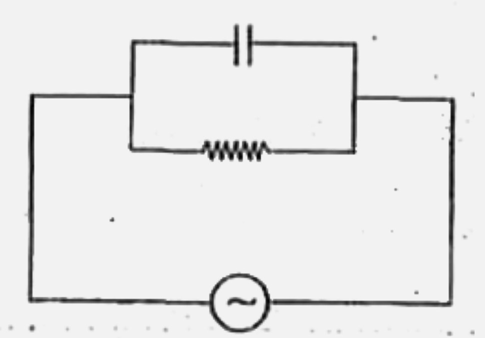
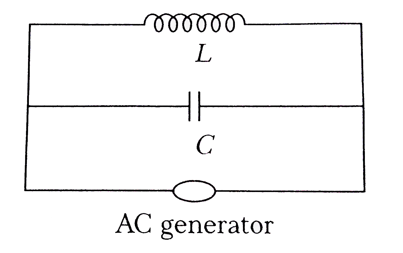
In the circuit shown in the figure , the alternating currents through inductor and capacitor are 1.2 and 1.0 A respectively . The current drawn from the generator is
A
0.4 A
B
0.2 A
C
1.0 A
D
1.2 A
Video Solution
Text Solution
The correct Answer is:B
|
Answer
Step by step video, text & image solution for In the circuit shown in the figure , the alternating currents through inductor and capacitor are 1.2 and 1.0 A respectively . The current drawn from the generator is by Physics experts to help you in doubts & scoring excellent marks in Class 12 exams.
Updated on:21/07/2023Similar Questions
Knowledge Check
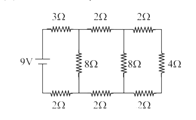
In the circuit shown in the figure, the current through
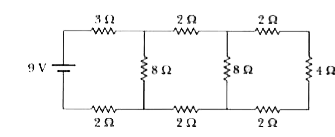 AThe 3Ω resistor is 0.50ABThe 3Ω resistor is 0.25ACThe 4Ω resistor is 0.50ADThe 4Ω resistor is 0.25A
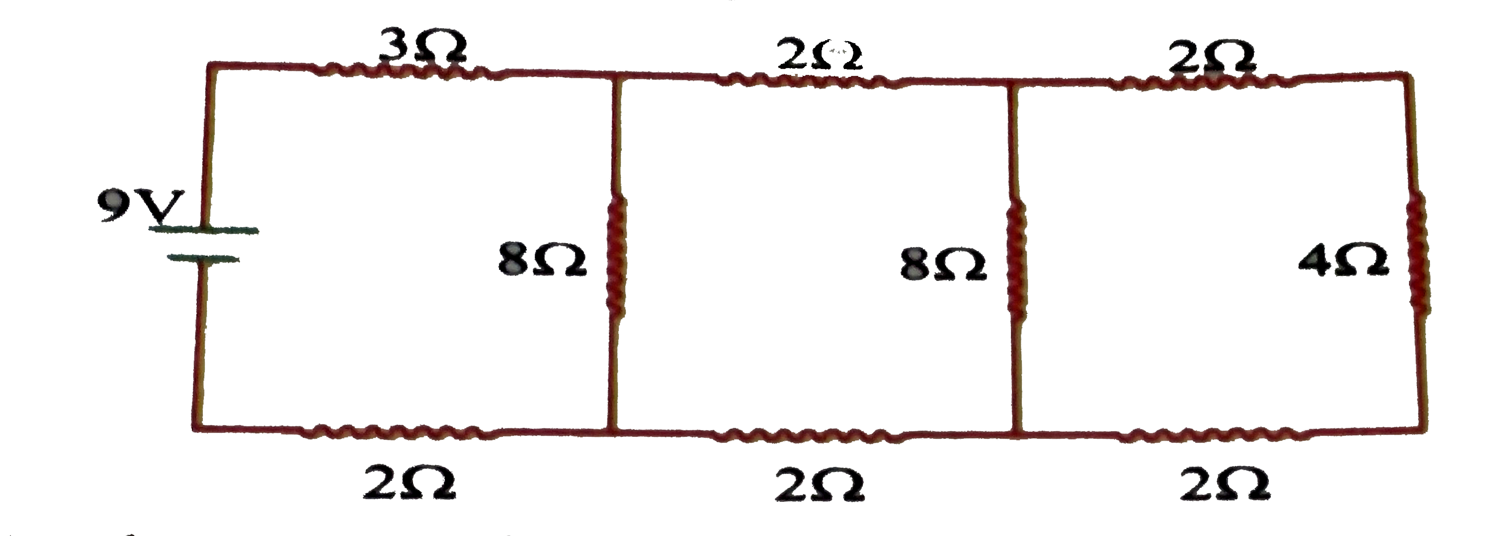
In the circuit shown in the figure, the current throughAthe 3Ω resistor is 0.50 ABthe 3Ω resistor is 0.25ACThe 4Ω resistor is 0.50 ADthe 4Ω resistor is 0.25AIn the circuit shown in the figure
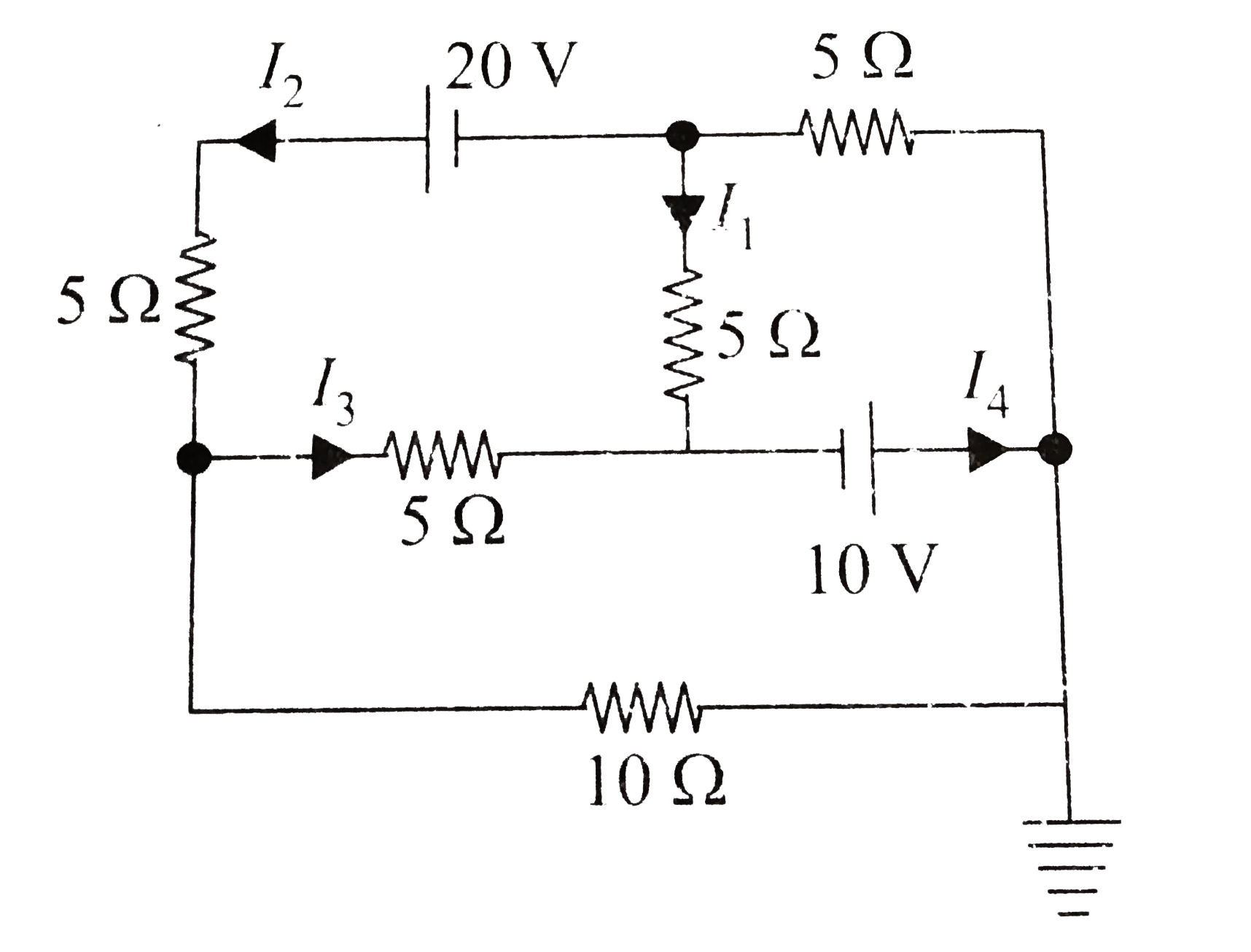 .
.
The value of current I1 isA2ABzeroC2.5 ADnone of these
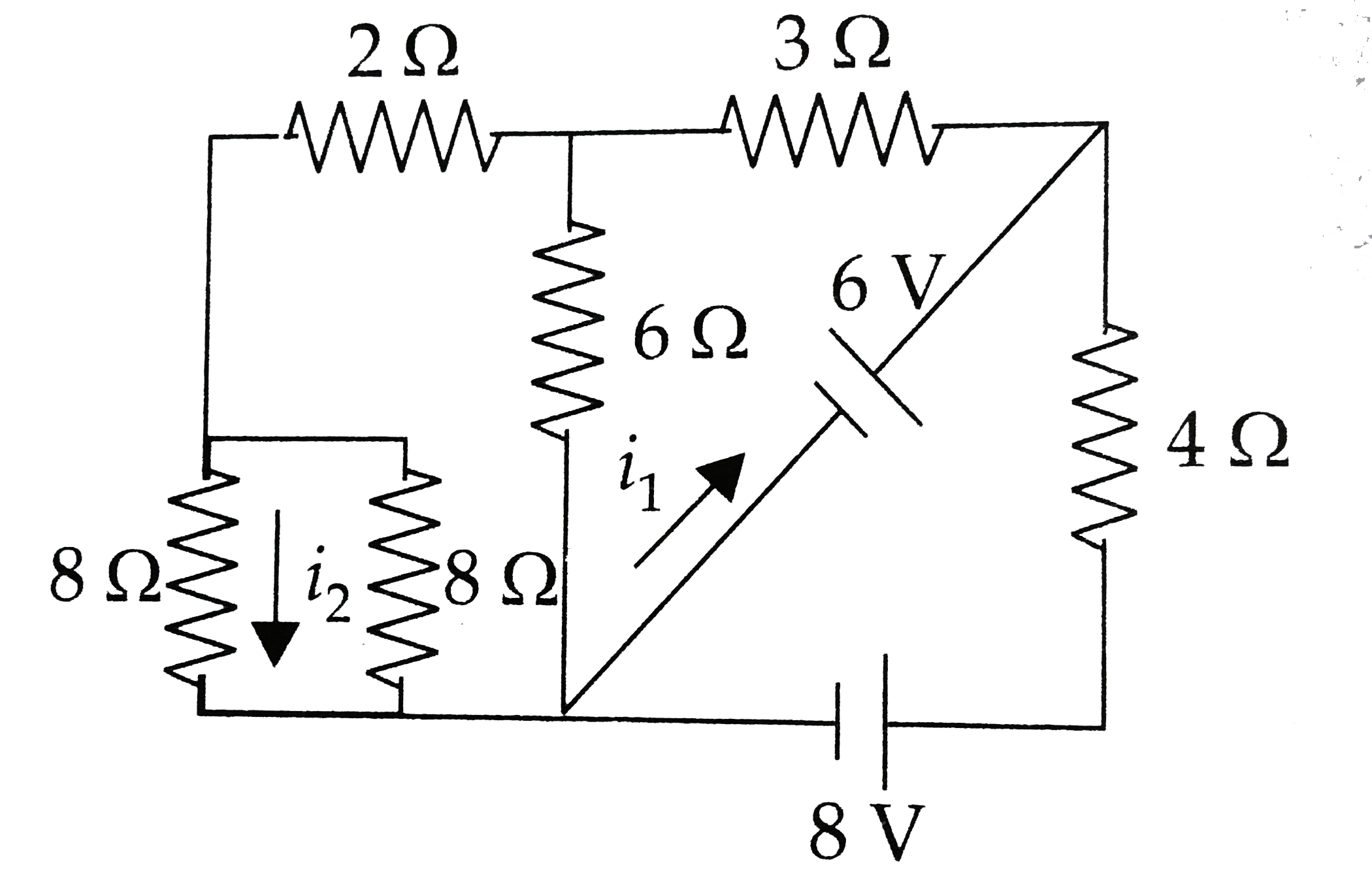
In the circuit shown in figure ,find the ratio of currents i1/i2.
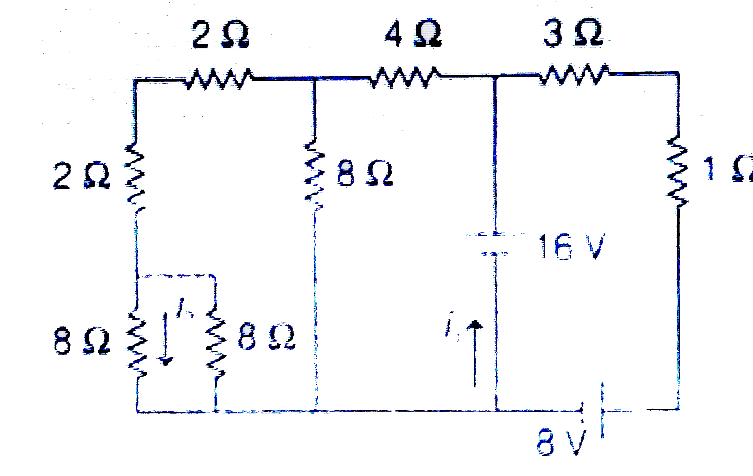
View SolutionIn the circuit shown in figure the current through
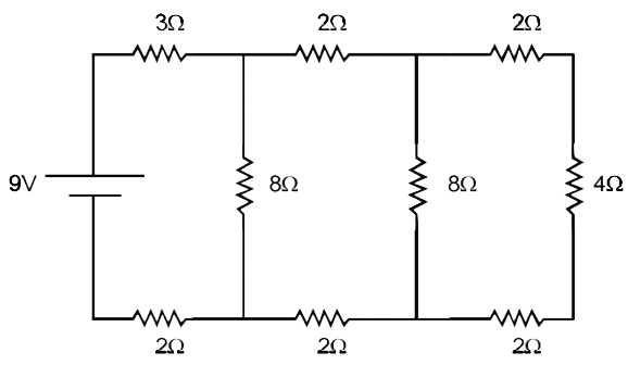
View SolutionIn the circuit as shown in figure, the ratio of current i1/i2 is
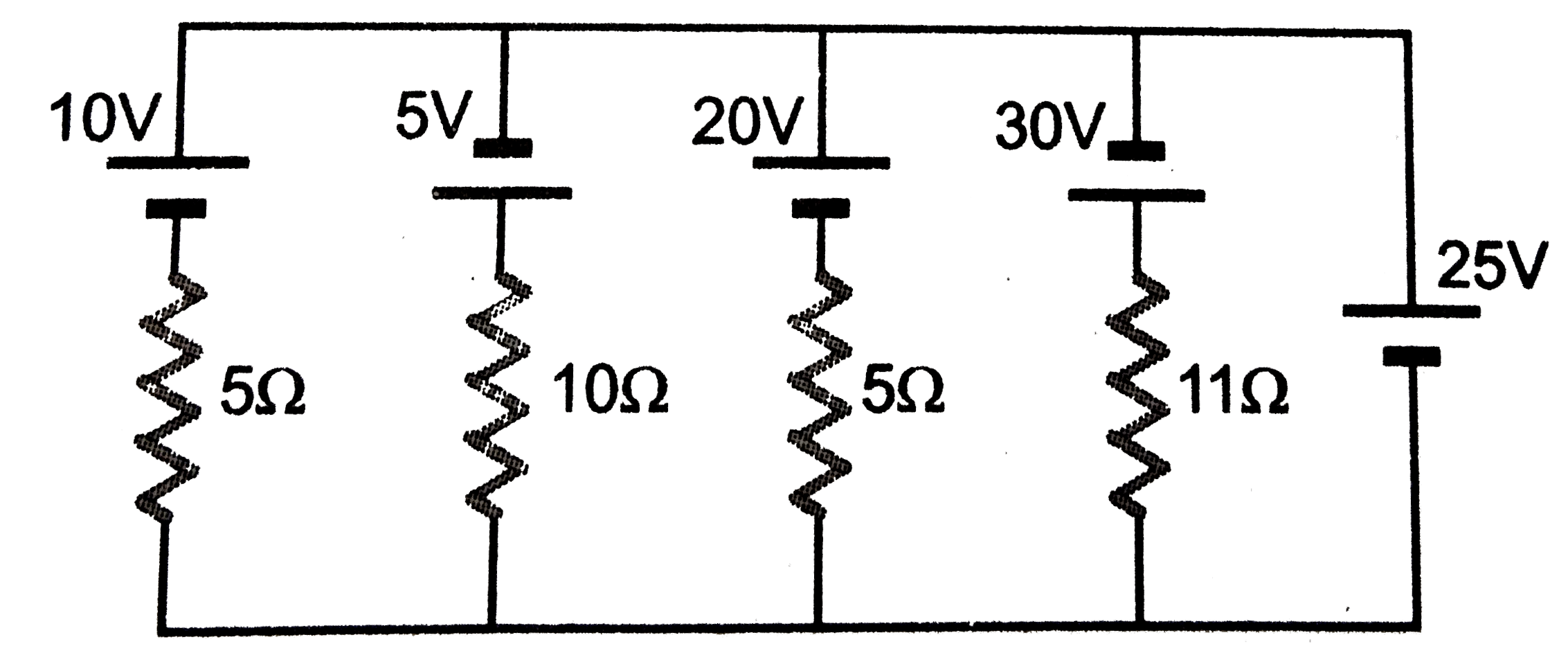
View SolutionIn the circuit shown in figure the current flowing through 25 V cell is
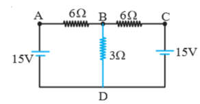
View SolutionIn the circuit shown in figure, find the current through the branch BD.
View Solution

