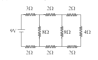
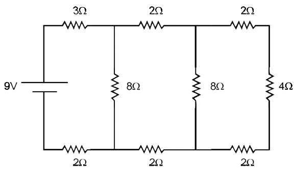
In the circuit shown in figure the current through
A
the 3Ω resistor is 0.50 A.
B
the 3Ω resistor is 0.25A
C
the 4Ω is 0.50A
D
the 4Ω resistor is 0.25A.
Video Solution
Text Solution
The correct Answer is:D
(d) The net resistance of the circuit is 9Ω as shown in the following figures.
 rArr (##JMA_CE_C13_042_S02.png)
I=VR=9V9Ω=1.0A.
The flow of current in the circuit is as follows.
|
Topper's Solved these Questions
Similar Questions
Knowledge Check
In the circuit shown in the figure, the current through
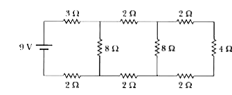 AThe 3Ω resistor is 0.50ABThe 3Ω resistor is 0.25ACThe 4Ω resistor is 0.50ADThe 4Ω resistor is 0.25A
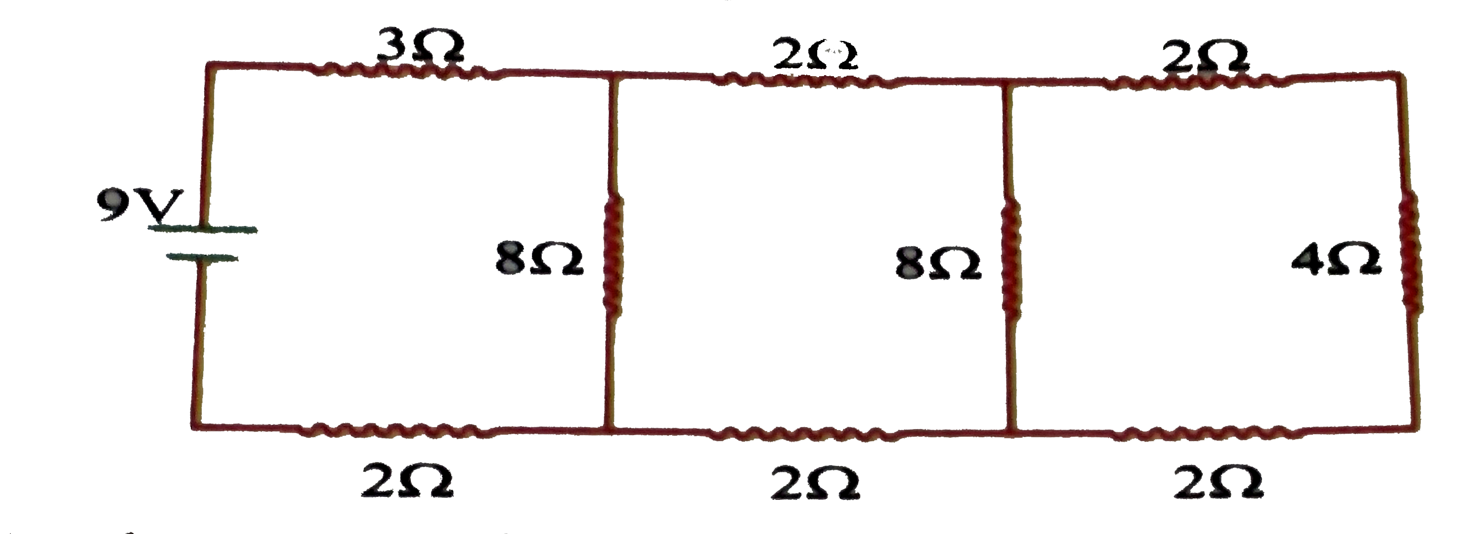
In the circuit shown in the figure, the current throughAthe 3Ω resistor is 0.50 ABthe 3Ω resistor is 0.25ACThe 4Ω resistor is 0.50 ADthe 4Ω resistor is 0.25AConsider the circuit shown in figure. The current through the battery a long time after the switch S is closed is:
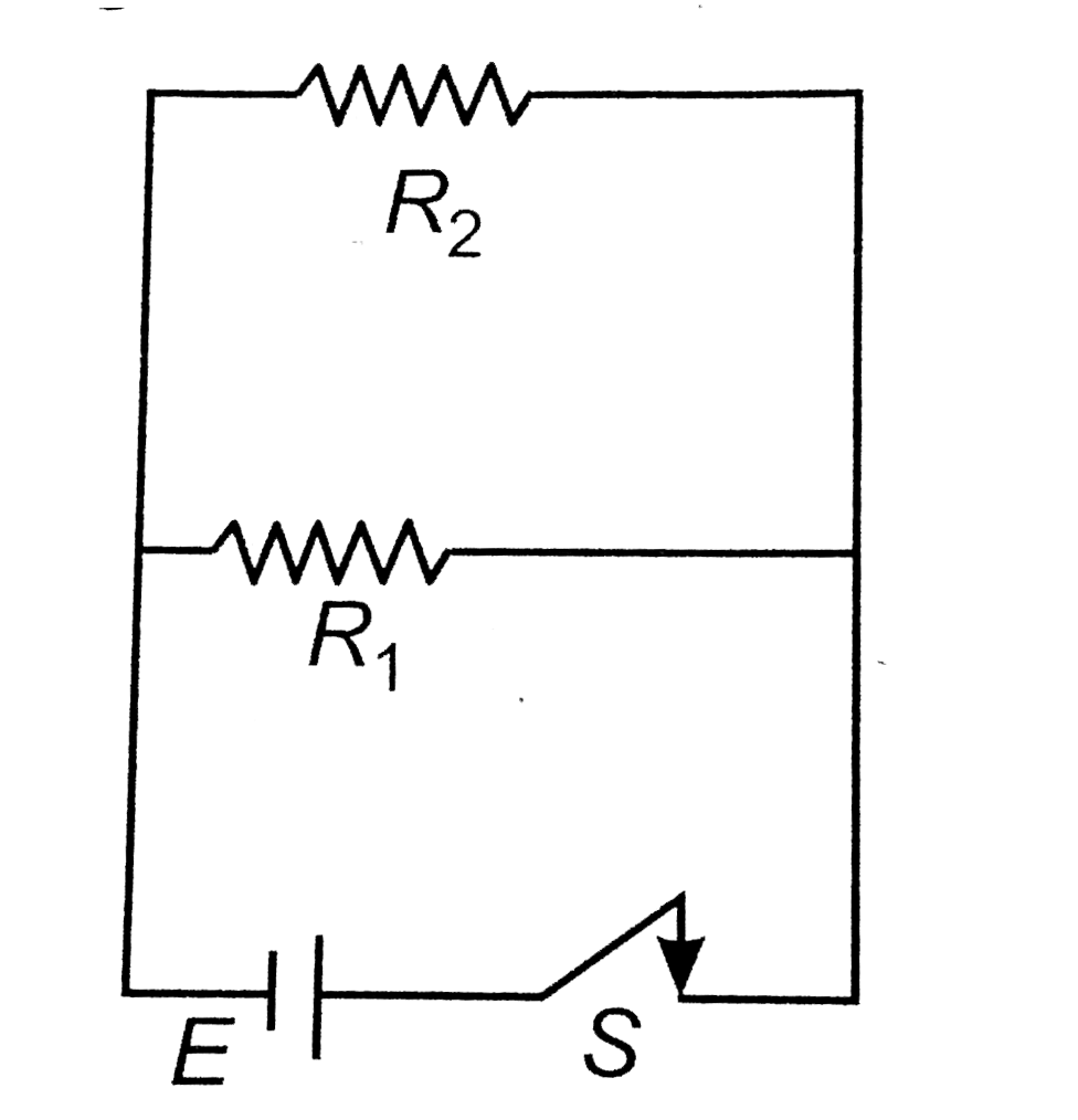 AER1BER2CER1+R2DE(R1+R2)(R1R2)
From the Zener diode circuit shown in figure, the current through the Zener diode is
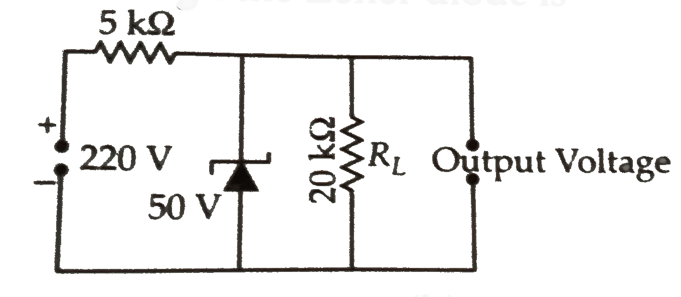
View SolutionFrom the Zener diode circuit shown in figure, the current through the Zener diode is

View SolutionIn the circuit shown in figure, find the current through the branch BD.
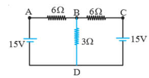
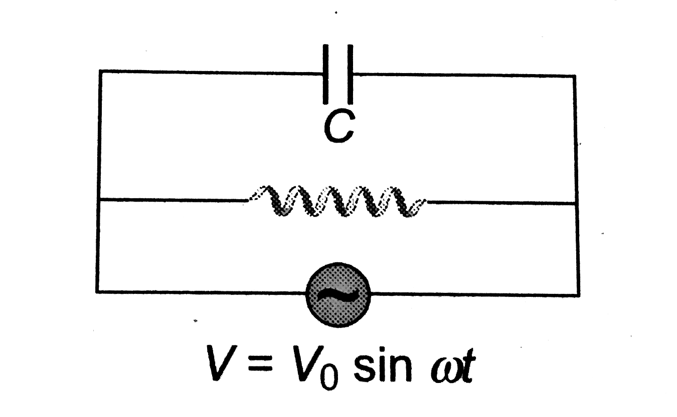
View SolutionFor the circuit shown in the figure, the current through the inductor is 0.9A while the current through the condenser is 0.4A. hence the current drawn from the generator is
View SolutionIn the circuit shown in figure
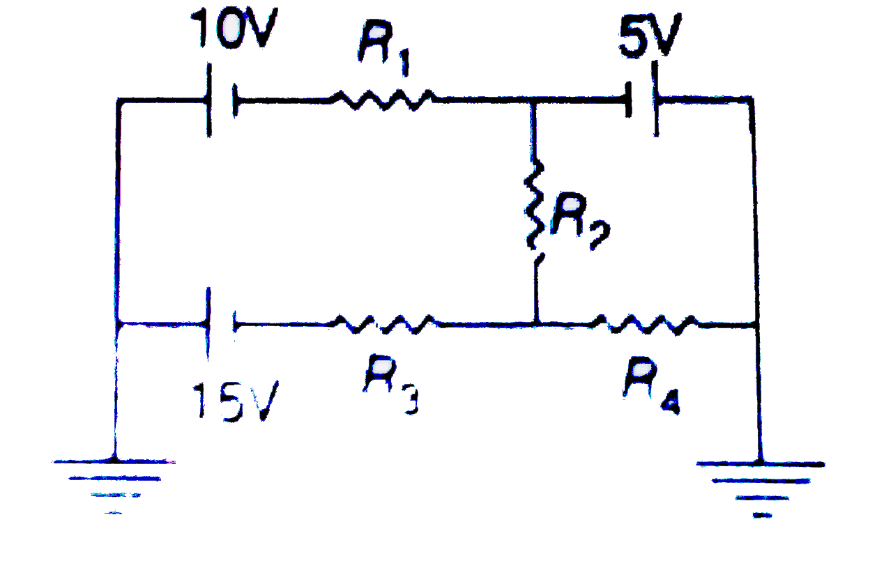
Current through R2 is zero if R4=2Ω and R3=4Ω In this case
View Solution

