The resistors R1,R2,R3 and R4 in the figure given below are all equal in value.
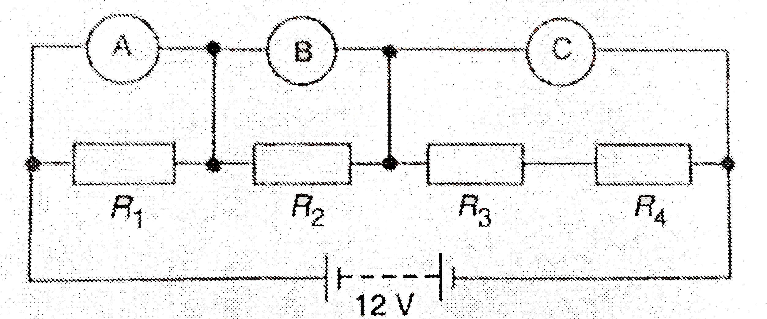
What would you expect the voltmeters A,B and C to read assuming that the connecting wires in the circuit have negligible resistance ?
The correct Answer is:A=3V;B=3V;C=6V
Step by step video, text & image solution for The resistors R_(1),R_(2),R_(3) and R_(4) in the figure given below are all equal in value. What would you expect the voltmeters A,B and C to read assuming that the connecting wires in the circuit have negligible resistance ? by Physics experts to help you in doubts & scoring excellent marks in Class 10 exams.
Topper's Solved these Questions
- BOOK - LAKHMIR SINGH & MANJIT KAURCHAPTER - ELECTRICITY EXERCISE - Very Short Answer Type Questions1videos
ELECTRICITY
- BOOK - LAKHMIR SINGH & MANJIT KAURCHAPTER - ELECTRICITY EXERCISE - Short Answer Type Questions2videos
ELECTRICITY
- BOOK - LAKHMIR SINGH & MANJIT KAURCHAPTER - ELECTRICITY EXERCISE - Sample Problem1videos
ELECTRICITY
- BOOK - LAKHMIR SINGH & MANJIT KAURCHAPTER - MAGNETIC EFFECT OF ELECTRIC CURRENT EXERCISE - NCERT BOOK2videos
MAGNETIC EFFECT OF ELECTRIC CURRENT
Similar Questions
5 resistances R1,R2,R3,R4,R5 are joined as shown in the figure.
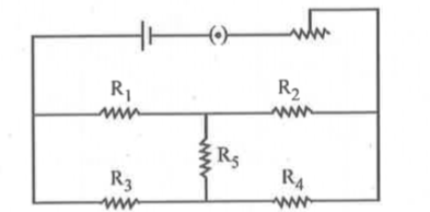
The values of R1,R2,R3andR4 are so adjusted that the current in the circuit does not change for any value of the resistance R5. This is possible for the following relationView SolutionIn the circuit diagram given below, three resistors R1,R2, and R3 of 5Ω,10Ω and 30Ω, respectively are connected as shown.
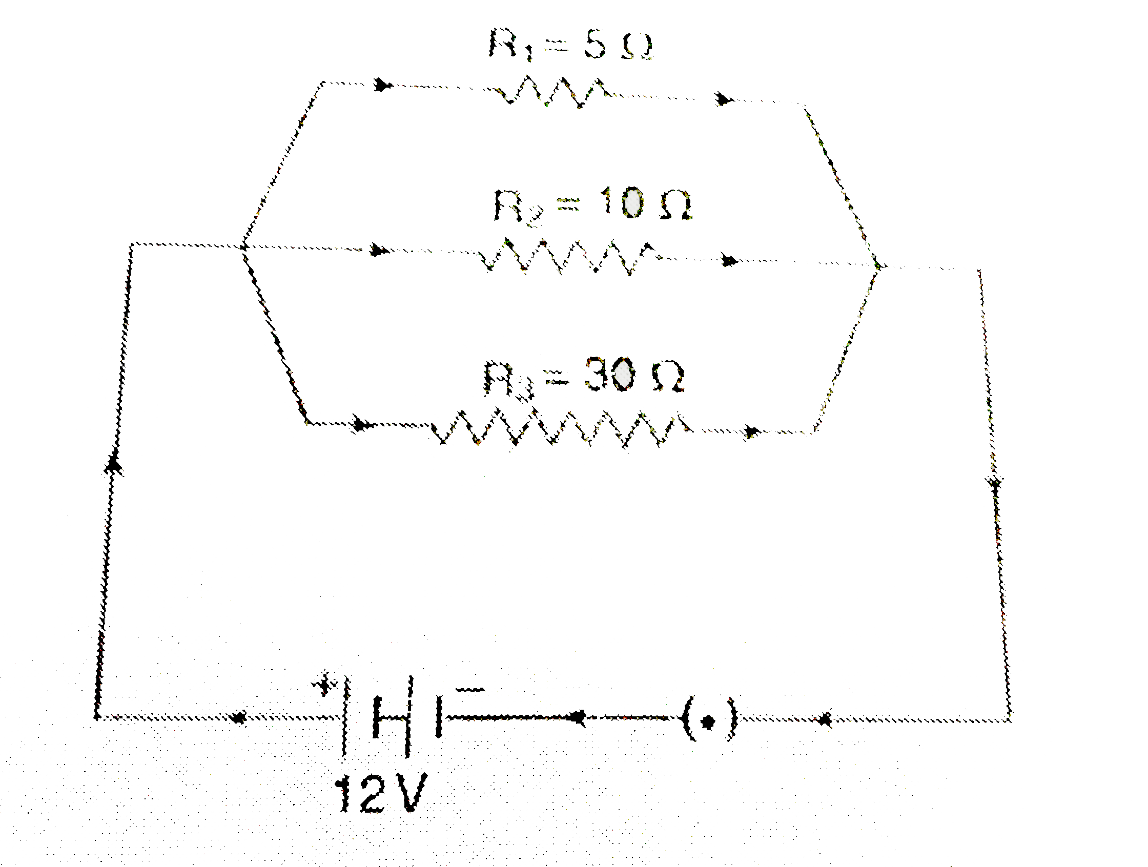
Calculate:
(a) current through each resistor.
(b) total current in the circuit.
(c) total resistance in the circuit.View Solution
Knowledge Check
- Question 1 - Select One
For three circuits, shown here

the same two resistors R1 and R2 have been connected in parallel in all the circuits but the voltmeter and the ammeter have been connected in three different positions. The relation between the three voltmeter and ammeter readings would be :AV1=V2=V3 and I1=I2=I3BV1≠V2≠V3 and I1=I2=I3CV1=V2=V3 and I1≠I2≠I3DV1≠V2≠V3 and I1≠I2≠I3 - Question 2 - Select One
In the circuit shown below, the ammeter A reads 5 A and the voltmeter V reads 20 V The correct value of resistance R is
 Aexactlt 4Ω.Bslightly greater than 4ΩCslightly less than 4ΩDzero
 - Question 3 - Select One
The ammeter, voltmeter and, resistors R1 and R2 connected in the circuit as shown below have been checked and found to be correct.
On plugging the key, the voltmeter reads 4.5 V but the ammeter reads 1.5 A. This is most likely because the wires joined to :
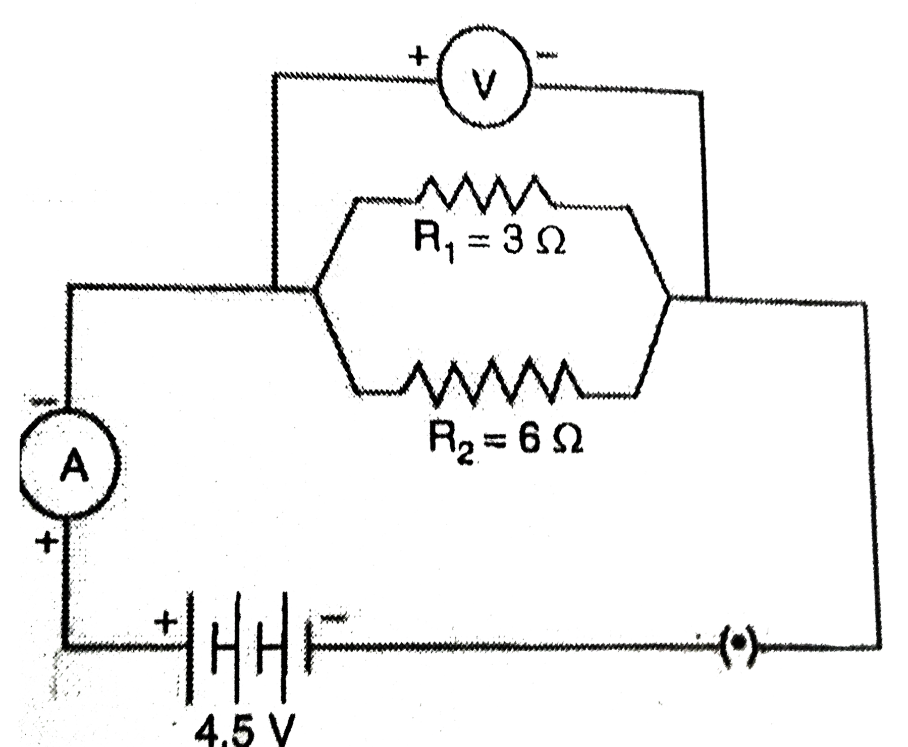 Aresistor R1 are looseBresistor R2 are looseCboth the resistors R1 and R2 are looseDammeter terminals are loose
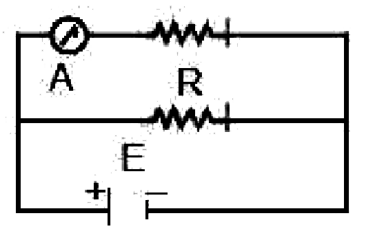
In the circuit shown below, if the value of R is increased then what will be the effect on the reading of ammeter if the internal resistance of cell is negligible-
 View Solution
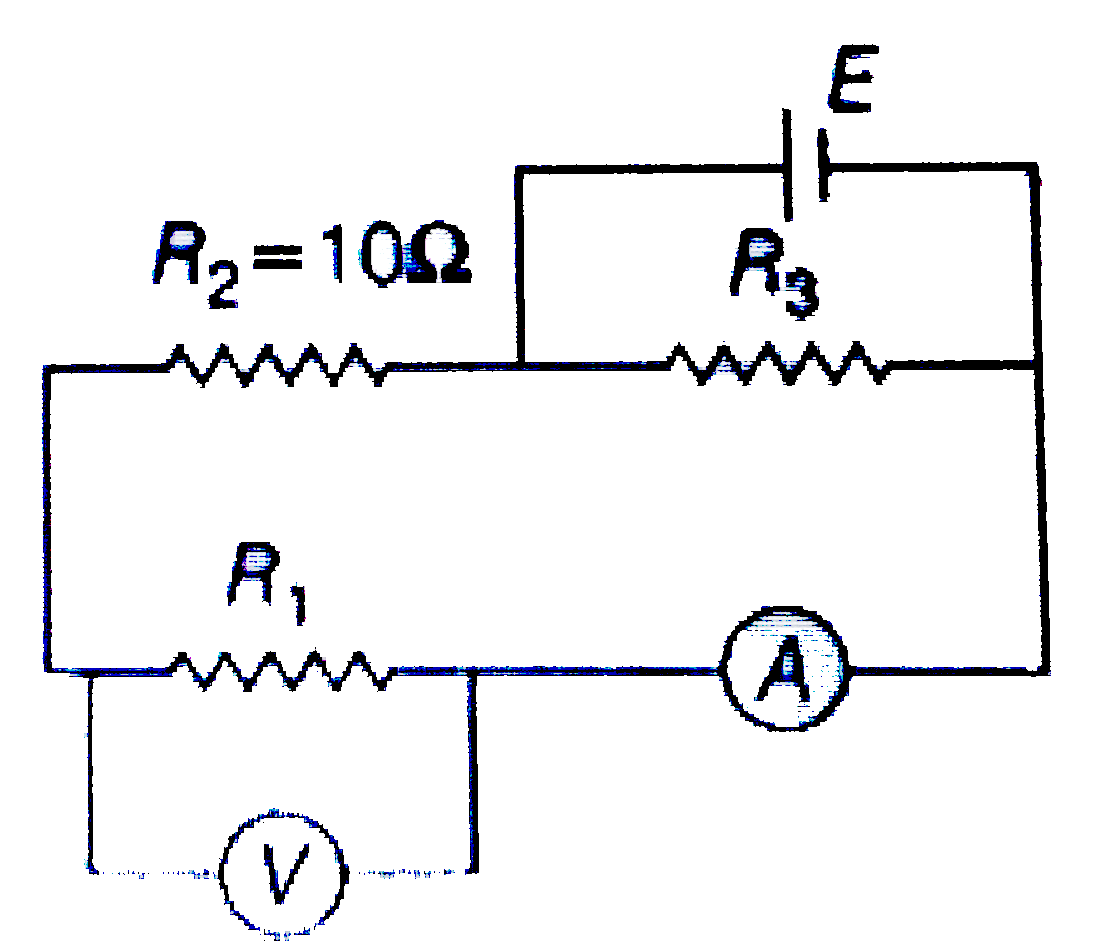
The power dissipated in resistor R3 shown in the figure is 15 W. The reading the ammeter is 500 mA and the reading of the voltmeter is 10 V. Ammeter, voltmeter and battery are ideal.
Find the resistance R1View SolutionThree resistors R1,R2 and R3 are to be combined to form an electrical circuit as shown in the figure. It is found that when R1R2andR3 are put respectively in positions A, B and C, the effective resistance of the circuit is 70 ΩWhen R2,R3andR1 are put respectively in position A, B and C the effective resistance is 35Ω and when R3,R1andR2 are respectively put in the position A, B and C, the effective resistance is 42Ω
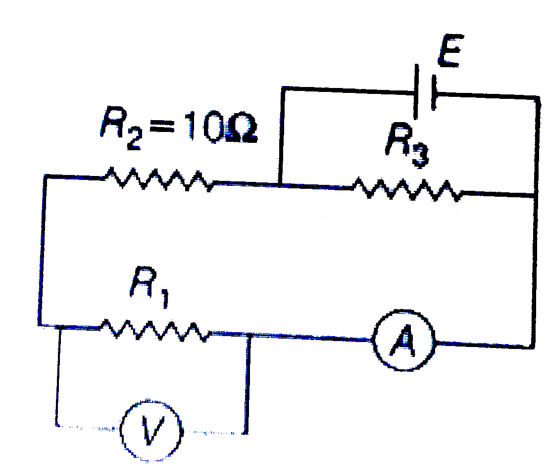
If R1,R2andR3 are all connected in parallel, the effective resistance will beView SolutionThe power dissipated in resistor R3 shown in the figure is 15 W. The reading the ammeter is 500 mA and the reading of the voltmeter is 10 V. Ammeter, voltmeter and battery are ideal.
Find the resistance R3View SolutionTo find the value of resistance R using Ohm's law, we are given four voltmeters as below. Which one will you prefer to be connected in the circuit?
View Solution

