Students A and B connect the two resistors R1 and R2 given to them in the manners shown below :

and then insert them at X and Y into the measuring circuit shown below :
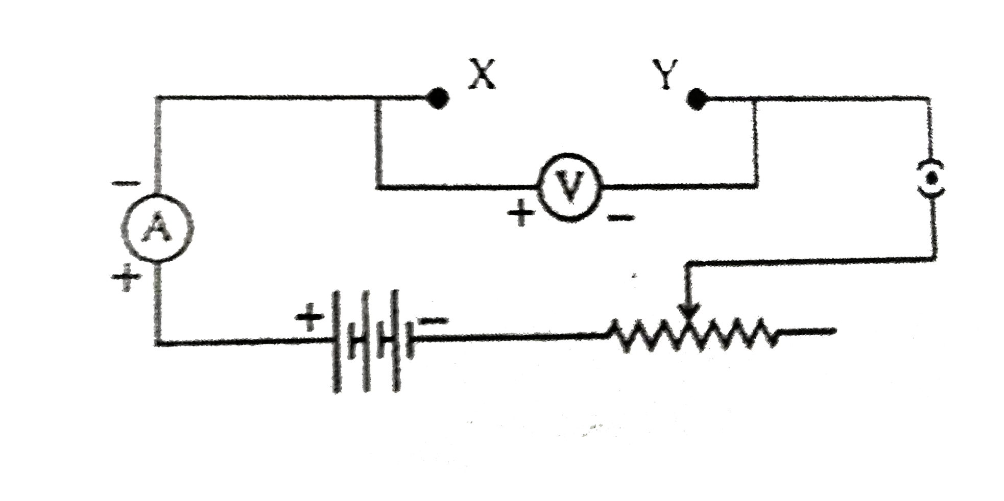
We can then say that
both the students will determine the equivalent resistance of the series combination of R1 and R2
both the students will determine the equivalent resistance of the parallel combination of R1 and R2
student A will determine the equivalent resistance of the series combination while student B will determine the equivalent resistance of the parallel combination of R1 and R2
student A will determine the equivalent resistance of the parallel combination while student B will determine the equivalent resistance of the series combination of R1 and R2
The correct Answer is:A
NA
Topper's Solved these Questions
- BOOK - LAKHMIR SINGH & MANJIT KAURCHAPTER - THE HUMAN EYE AND THE COLOURFUL WORLD EXERCISE - Long Answer Type Question3videos
THE HUMAN EYE AND THE COLOURFUL WORLD
- BOOK - LAKHMIR SINGH & MANJIT KAURCHAPTER - THE HUMAN EYE AND THE COLOURFUL WORLD EXERCISE - NCERT Book14videos
THE HUMAN EYE AND THE COLOURFUL WORLD
- BOOK - LAKHMIR SINGH & MANJIT KAURCHAPTER - THE HUMAN EYE AND THE COLOURFUL WORLD EXERCISE - Long Answer Type Questions2videos
THE HUMAN EYE AND THE COLOURFUL WORLD
- BOOK - LAKHMIR SINGH & MANJIT KAURCHAPTER - TEST PAPER 4EXERCISE - SECTION A10videos
TEST PAPER 4
Similar Questions
two resistors R and 2R are connected in series in an electric circuit. The thermal energy developed in R and 2R are in the ratio
View SolutionA student did the experiment to find the equivalent resistance of two given resistors, R1 and R2 first when they are connected in series and next when they are connected in parallel. The two values of the equivalent resistance obtained by him were Rs and Rp respectively. Compare Rs and Rp.
View Solution
Knowledge Check
- Question 1 - Select One
Three students (A), (B) and (C) connect their two given resistors R1 and R2 in the manners shown below :

They connect the terminals marked X and Y above to the terminals marked X and Y in the circuit given below:
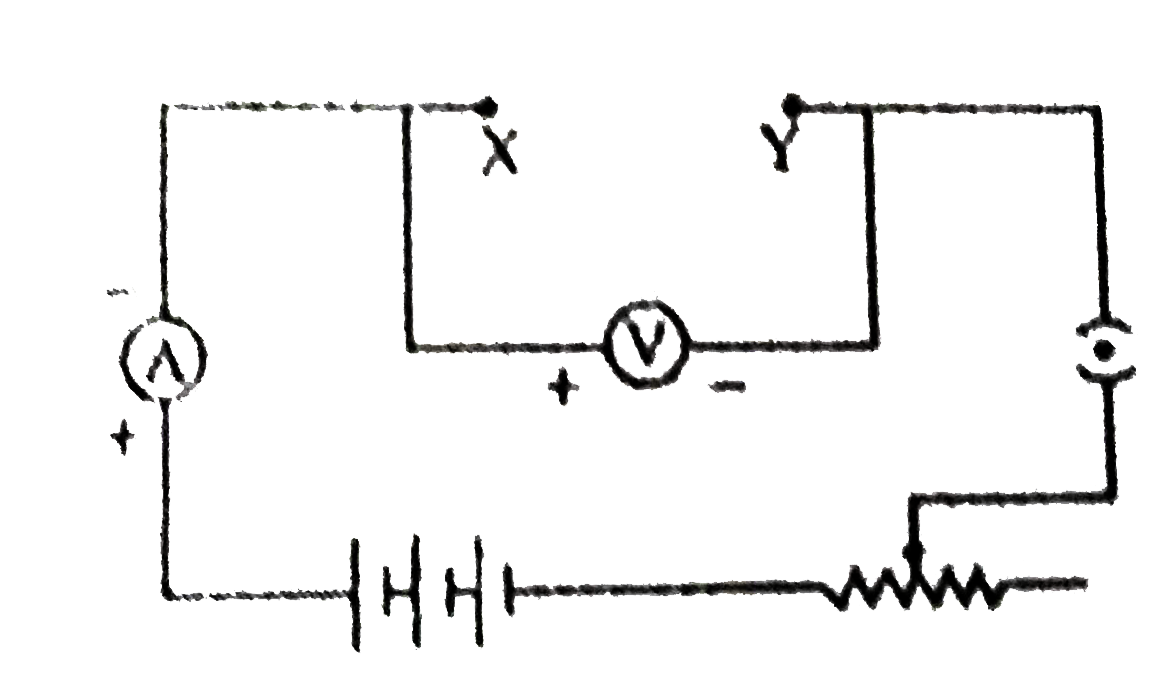
The record the Ammeter readings (I) for different positions of the rheostat and the corresponding Voltmeter readings (V).
The average value of the ratio V/I in their observations would be minimum for :Astudents (A) and (B) onlyBstudents (B) and (C) onlyCstudents (C) and (A) onlyDstudent (A) only - Question 2 - Select One
Two students (A) and (B) connect their two given resistors R1 and R2 in the menners shown below :

Student (A) connects the terminals marked (b1) and (C1) while student (B) connects the terminals marked (d2) and (c2) in their respective circuits at the points marked X and Y.
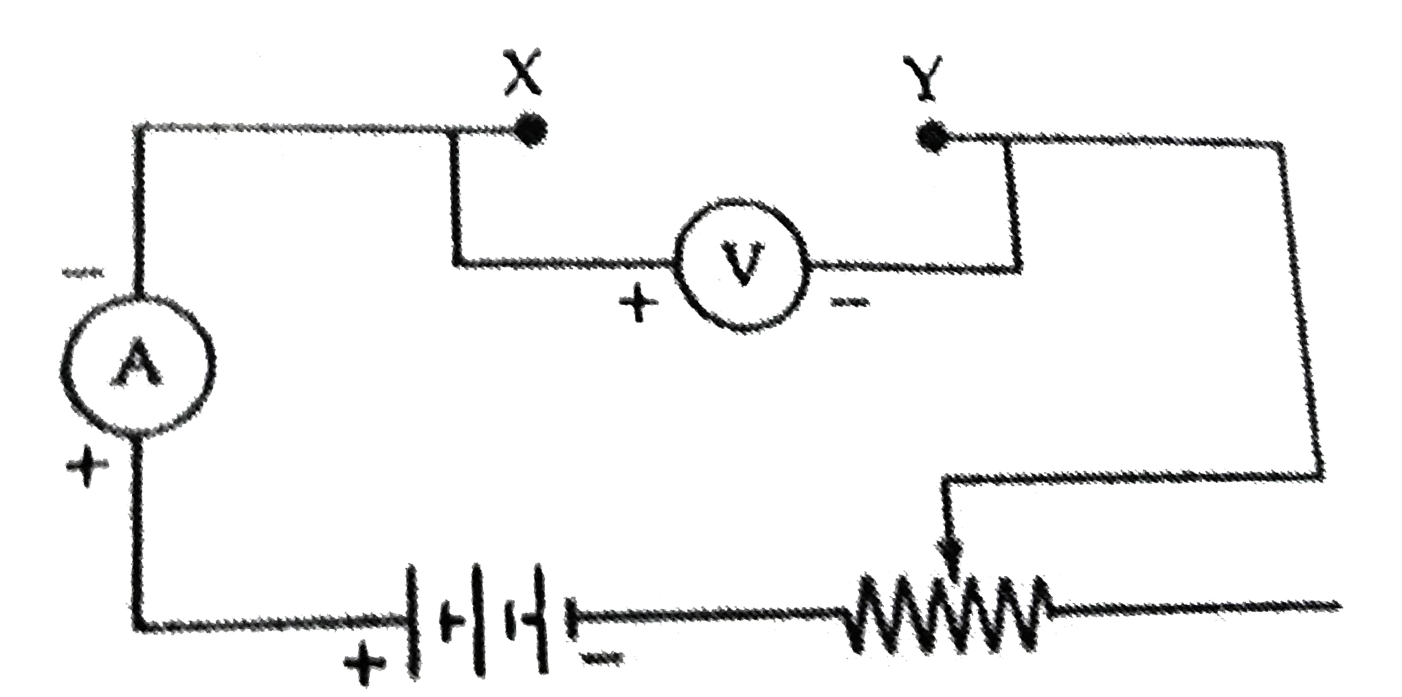
Which one of the following is correct in relation to above arrangements ?Aboth the students will determine the equivalent resistance of the series combination of the two resistors.Bboth the students will determine the equivalent resistance of the parallel combination of the two resistors.Cstudent (A) will determine the equivalent resistance of the series combination while student (B) will determine the equivalent resistance of the parallel combination of the two resistors.Dstudent (A) will determine the equivalent resistance of the parallel combination while student (B) will determine the equivalent resistance of the series combination of the two resistors. - Question 3 - Select One
A student carries out the experiment for studying the dependence of current (I) flowing through a resistor system of R1 and R2 on the potential difference (V) applied to it by connecting the resistor system to points X and Y of the measuring circuit as shown :
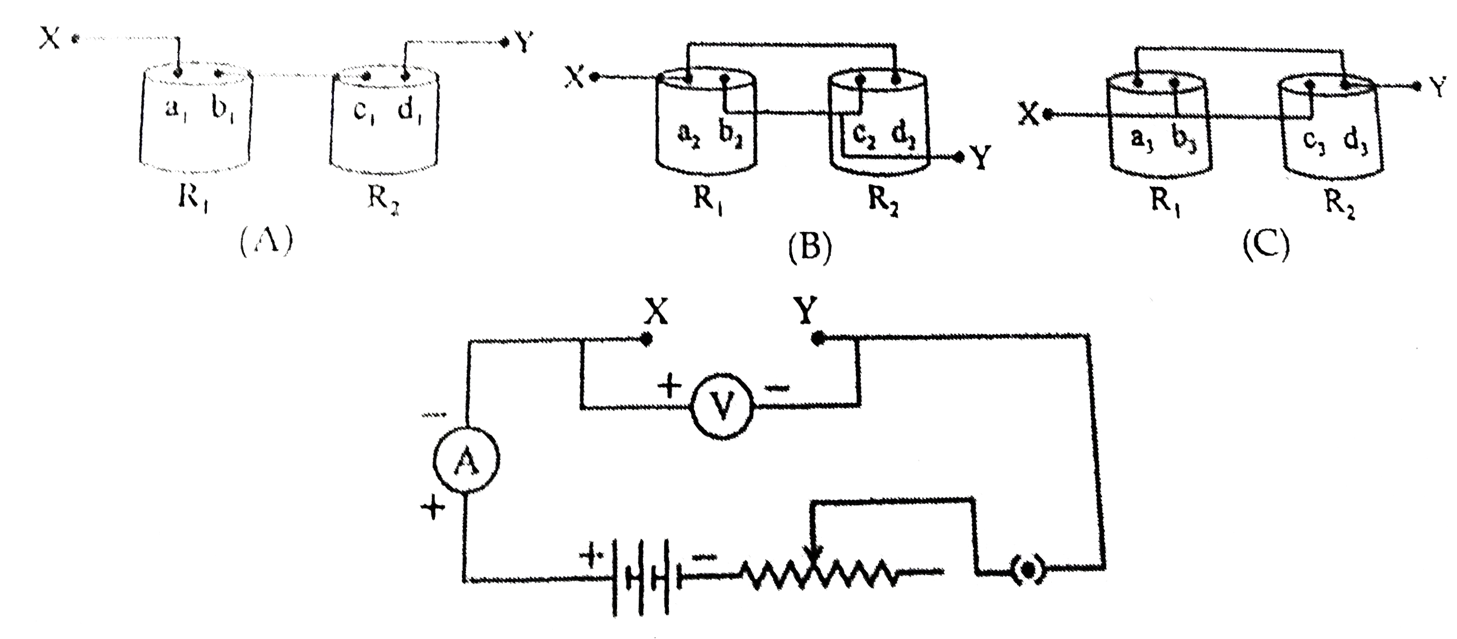
The average value of the ratio V/I, of his observations, would then be equalAonly in cases A and BBonly in cases B and CConly in cases C and ADall the three cases
The values of resistance marked on the coils R1 and R2 are found to be correct. A student connects the given resistors in the following manner (as shown in Figure 1).

He then connects the terminals marked X and Y of the above combination of resistors R1 and R2 to the terminals marked X and Y in the circuit (shown in Figure 2).
The average value of the ratio V/I in the obervations recorded in the circuit would be :View SolutionIn the circuit shown below, the ammeter reading is zero. Then, the value of the resistance R is
 View Solution
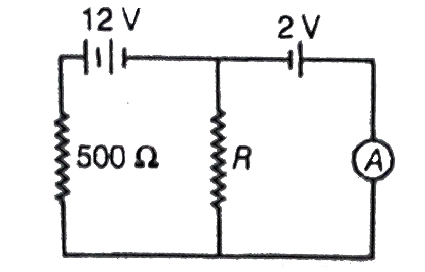
In the circuit shown below, the ammeter reading is zero. Then, the value of the resistance R is
 View Solution
To get an output y=1 from the circuit shown below, the input must be
 View Solution
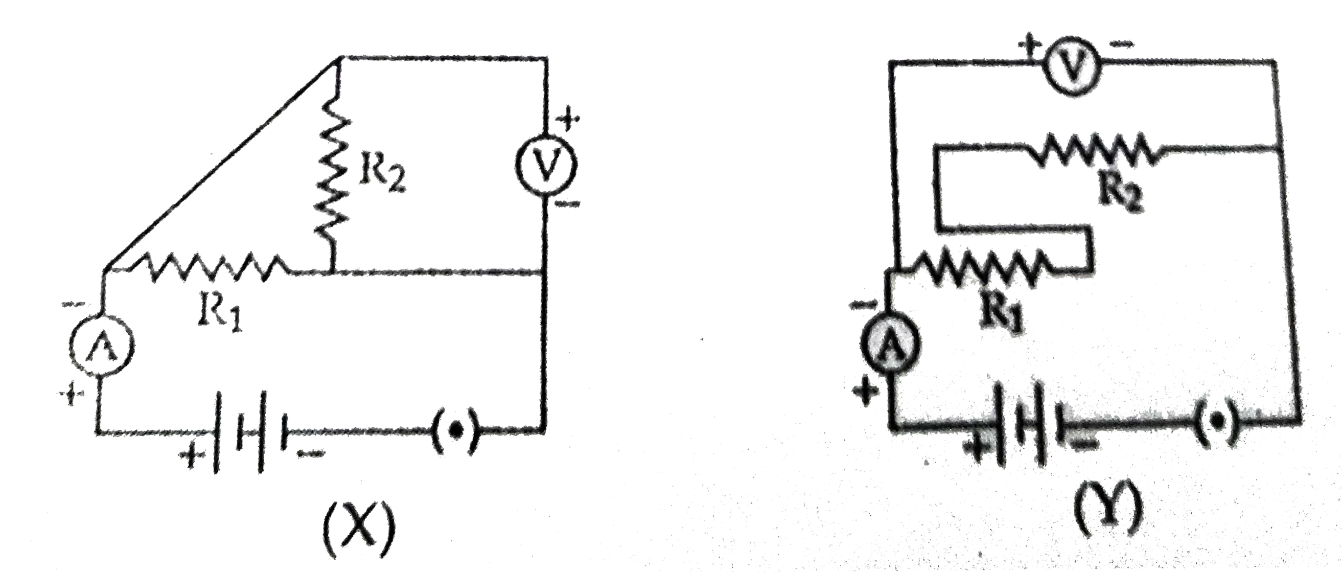
The only correct statement for the two circuits (X) and (Y) shown below is :
 View Solution

