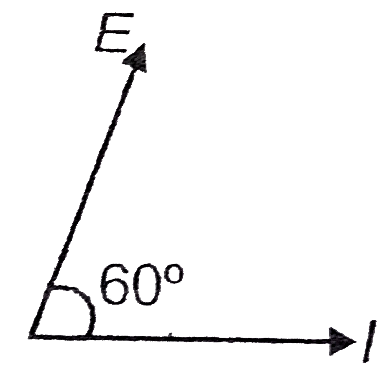
In series LCR circuit voltage leads the current. When
(Given that ω0 = resonant angular frequency)
ω<ω0
ω=ω0
ω>ω0
None of these
The correct Answer is:C
To determine the condition under which the voltage leads the current in a series LCR circuit, we need to analyze the relationship between the angular frequency (ω) and the resonant angular frequency (ω₀).
1. Understand the Circuit: In a series LCR circuit, we have an inductor (L), a capacitor (C), and a resistor (R) connected in series. The behavior of the circuit is influenced by the frequency of the applied voltage.
2. Resonant Frequency: The resonant angular frequency (ω₀) is given by the formula:
ω0=1√LC
At this frequency, the inductive reactance (X_L = ωL) and capacitive reactance (X_C = \frac{1}{ωC}) are equal, leading to a purely resistive circuit.
3. Phase Relationship: In an LCR circuit:
- If the applied frequency (ω) is less than the resonant frequency (ω₀), the circuit is capacitive, and the current leads the voltage.
- If the applied frequency (ω) is greater than the resonant frequency (ω₀), the circuit is inductive, and the voltage leads the current.
4. Condition for Voltage Leading Current: Therefore, for the voltage to lead the current, the condition must be:
ω>ω0
5. Conclusion: Hence, the final answer is that in a series LCR circuit, the voltage leads the current when the applied frequency (ω) is greater than the resonant frequency (ω₀).
Final Answer:
Voltage leads the current in a series LCR circuit when:
ω>ω0
ω0=1√LC
At this frequency, the inductive reactance (X_L = ωL) and capacitive reactance (X_C = \frac{1}{ωC}) are equal, leading to a purely resistive circuit.
- If the applied frequency (ω) is less than the resonant frequency (ω₀), the circuit is capacitive, and the current leads the voltage.
- If the applied frequency (ω) is greater than the resonant frequency (ω₀), the circuit is inductive, and the voltage leads the current.
ω>ω0
Voltage leads the current in a series LCR circuit when:
ω>ω0
Similar Questions
Phase relationship between current (l) and applied voltage (E) for a series LCR circuit is shown here. ω0 = Resonant angular frequency of the circuit and ω= Applied angular frequency .

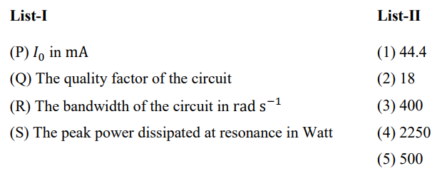
View SolutionA series LCR circuit is connected to a 45sin(ωt) Volt source. The resonant angular frequency of the circuit is 105rads−1 and current amplitude at resonance is l0. When the angular frequency of the source is ω=8×10⁴rads−1 , the current amplitude in the circuit is 0.05I0. If L=50mH, match each entry in List-I with an appropriate value from List-II and choose the correct option.

View Solution
Knowledge Check
In series LCR circuit at resonance
APower factor is zeroBPower developed across the resistor is maximumCPower developed across the inductor is zeroDBoth (2) & (3)In series LCR circuit at resonance,
Acurrent is maximum and impedance is maximumBcurrent is maximum and impedance is minimumCcurrent is minimum and impedance is maximumDcurrent is minimum and pmpedance is minimumIn series LCR circuit at resonance,
Acurrent is maximum and voltage is minimumBcurrent is maximum and voltage is maximumCcurrent is minimum and voltage is maximumDcurrent is minimum and voltage is minimum
In a series LCR circuit, at resonance the
View SolutionIn a series LCR circuit, at resonant frequency.
View SolutionAssertion : In series L−C−R circuit, voltage will lead the current function for frequency greater than the resonance frequency.
Reason : At resonance frequency, phase difference between current function and voltage function is zero.
View SolutionAssertion: In series L−R circuit voltage leads the current.
Reason: In series L−C circuit leads the voltage.
View SolutionIn R−L−C series circuit, we have same current at angular frequencies ω1 and ω2. The resonant frequency of circuit is
View Solution
