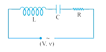
A : The chief characteristic of series resonant circuit is voltage magnification.
R : At resonance the voltage drop across inductance (or capacitance) is Q times the applied voltage.
If both Assertion & Reason are true and the reason is the correct explanation of the assertion, then mark (1)
If both Assertion & Reason are true but the reason is not the correct explanation of the assertion, then mark (2)
If Assertion is true statement but Reason is false, then mark (3)
If both Assertion and Reason are false statement, then mark (4)
The correct Answer is:A
To analyze the given statements regarding a series resonant circuit, we will break down the assertion (A) and reason (R) step by step.
Step 1: Understanding the Assertion (A)
The assertion states that "The chief characteristic of a series resonant circuit is voltage magnification."
- In a series resonant circuit, at resonance, the impedance is minimized, and the circuit allows maximum current to flow.
- This results in a significant increase in the voltage across the inductor (L) and capacitor (C) compared to the applied voltage (V).
- Therefore, the assertion is correct as voltage magnification is indeed a characteristic of series resonant circuits.
Step 2: Understanding the Reason (R)
The reason states that "At resonance, the voltage drop across inductance (or capacitance) is Q times the applied voltage."
- The quality factor (Q) is defined as the ratio of the reactance (either inductive or capacitive) to the resistance in the circuit:
Q=XLRorQ=XCR
- At resonance, the voltage across the inductor (V_L) or the capacitor (V_C) can be expressed as:
VL=Q⋅VRandVC=Q⋅VR
where VR is the voltage across the resistor.
- Since the voltage across the inductor or capacitor can be Q times the voltage across the resistor, the reason is also correct.
Step 3: Conclusion
Both the assertion (A) and the reason (R) are correct, and the reason correctly explains the assertion.
Final Answer:
Both A and R are true, and R is the correct explanation of A.
---
The assertion states that "The chief characteristic of a series resonant circuit is voltage magnification."
- In a series resonant circuit, at resonance, the impedance is minimized, and the circuit allows maximum current to flow.
- This results in a significant increase in the voltage across the inductor (L) and capacitor (C) compared to the applied voltage (V).
- Therefore, the assertion is correct as voltage magnification is indeed a characteristic of series resonant circuits.
The reason states that "At resonance, the voltage drop across inductance (or capacitance) is Q times the applied voltage."
- The quality factor (Q) is defined as the ratio of the reactance (either inductive or capacitive) to the resistance in the circuit:
Q=XLRorQ=XCR
- At resonance, the voltage across the inductor (V_L) or the capacitor (V_C) can be expressed as:
VL=Q⋅VRandVC=Q⋅VR
where VR is the voltage across the resistor.
- Since the voltage across the inductor or capacitor can be Q times the voltage across the resistor, the reason is also correct.
Both the assertion (A) and the reason (R) are correct, and the reason correctly explains the assertion.
Both A and R are true, and R is the correct explanation of A.
Similar Questions
Knowledge Check
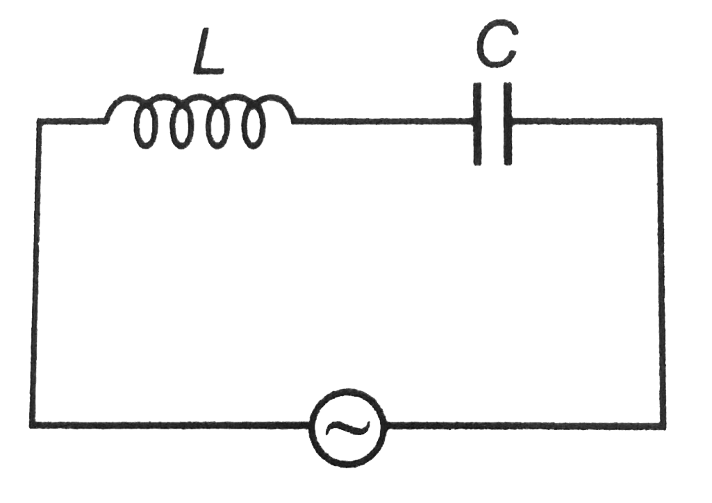
The voltage across inductor and condenser at resonance is
AzeroBof equal magnitude and in phaseCof equal magnitude and out of phase by πDof difference magnitudes and out of phase by πIn a series LCR circuit, the voltage across the inductance and capacitance are not
Aout of phase with voltage across resistance by 90∘Bequal in magnitude at resonanceCout of phase with each other by 180∘Din phase with the source voltageVoltage magnification factor of a series resonance circuit is
AQ=ωL/RBQ=1/ωCRCboth a and bDneither a nor b
In parallel resonant circuit, the current and voltage at resonance are
View SolutionIn series resonant circuit, at resonance the phase difference between the voltage across inductor and voltage across condenser is
View SolutionIn a series L−C circuit, the applied voltage is V0. if omega is very low, then the voltage drop across the inductor VL and capacitor VC are
 .
.
View SolutionIn an LCR series circuit the voltages across R,L and C at resonance are 40Vand60V respectively the applied voltage is .
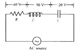
View SolutionIn series LCR circuit, the voltages across R, L and C shown in figure. The voltage of applied source is

View Solution


