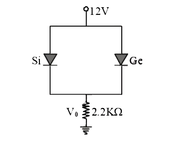
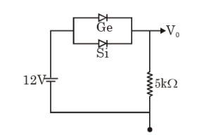
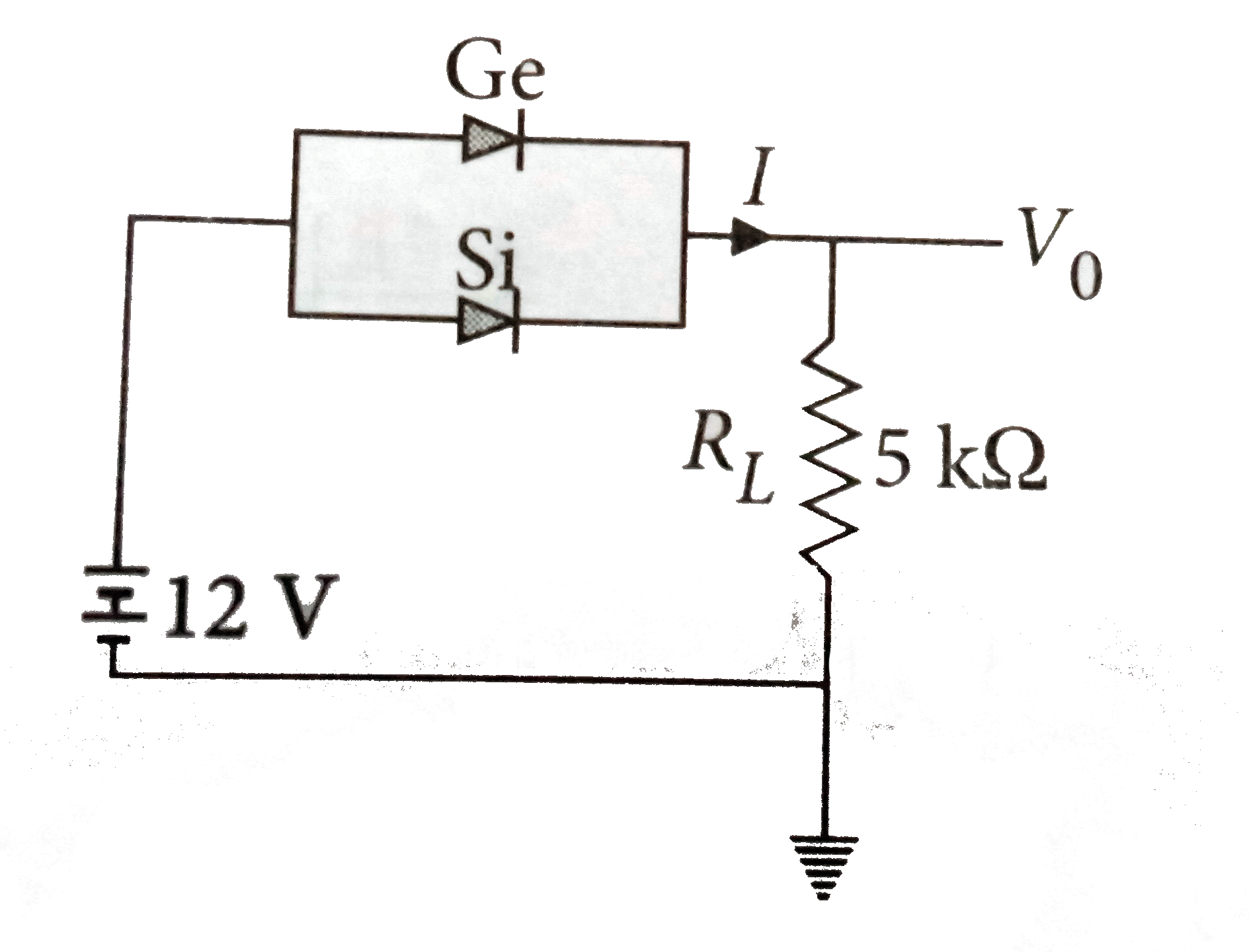
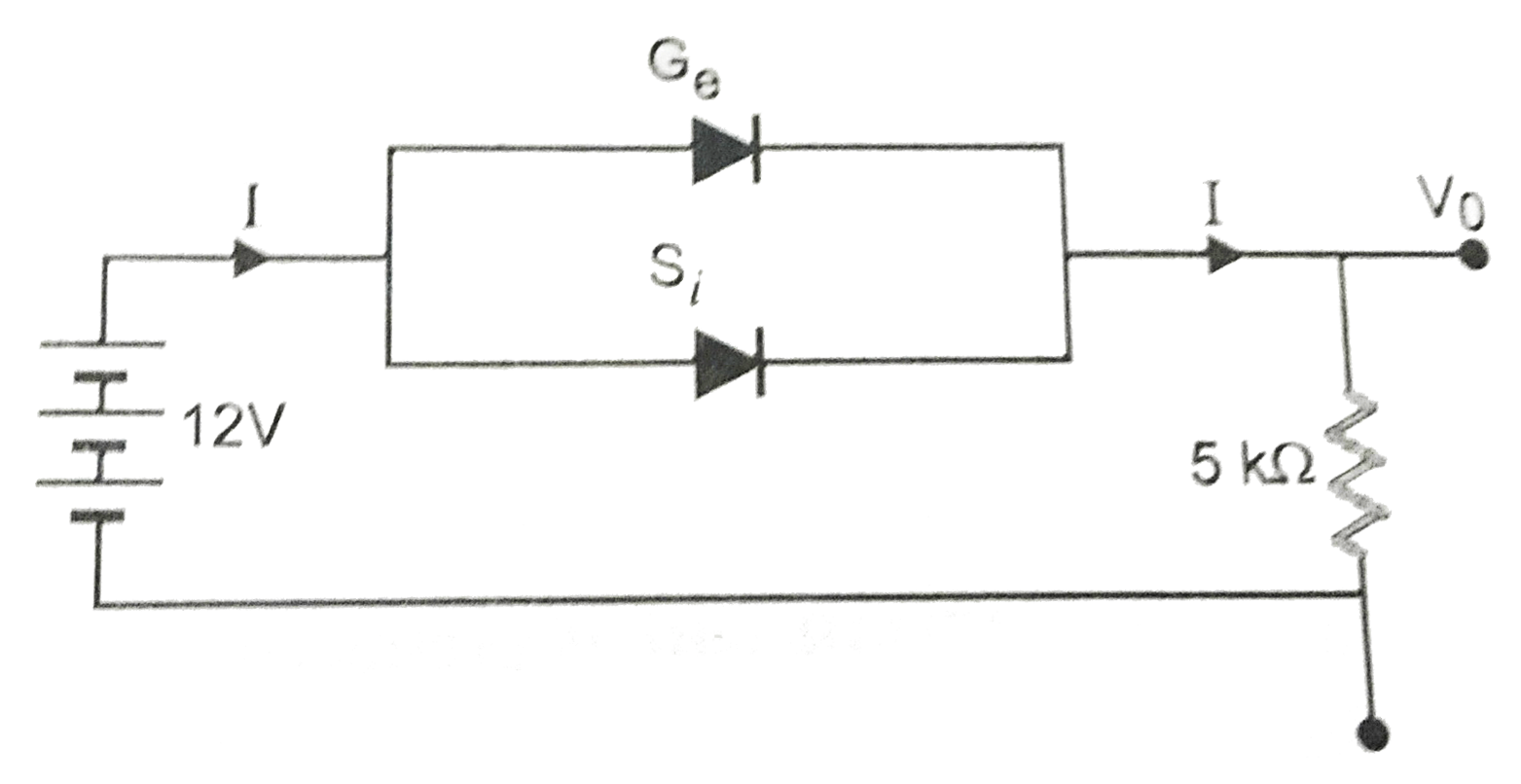
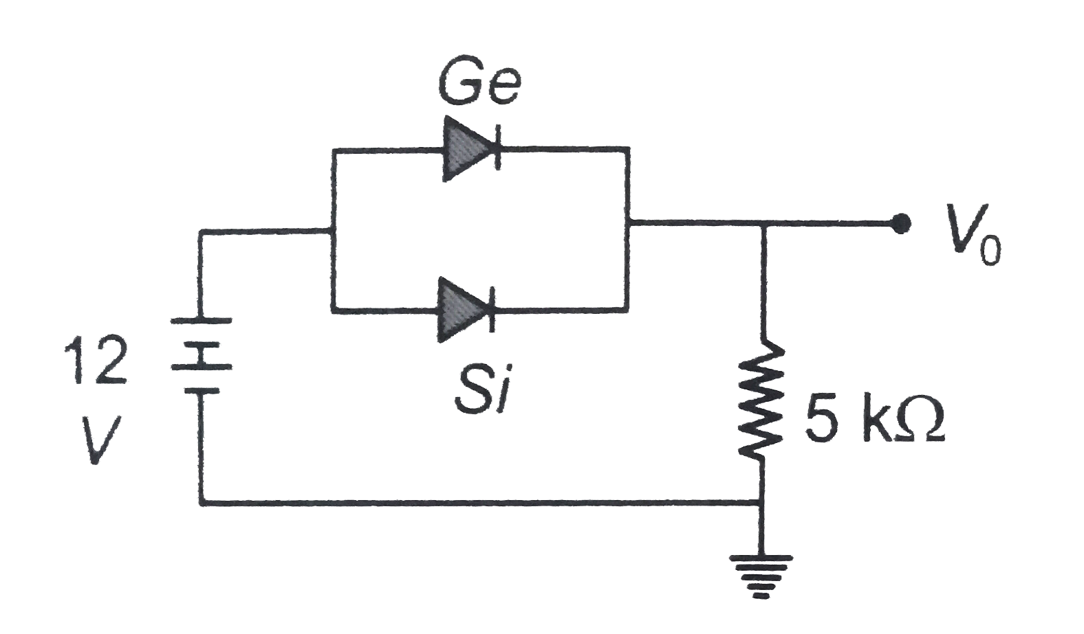
In the circuit shown in figure, the silicon and germanium diodes start conducting at 0.7 V and 0.3 V respectively. What are the values of V0 and I?
12 V, 2.4 mA
11.7 V, 2.34 mA
11.3 V, 2.26 mA
11 V, 2.2 mA
The correct Answer is:B
The germanium diode will start conducting before the silicon diode does so. The voltage across Ge = 0.3 V. The output voltage V0 is the voltage across R= 12 -0.3 = 11.7 V
The current I =11.7V5kΩ=11.75×103
=2.34×10⁻³A=2.34mA
Topper's Solved these Questions
- BOOK - NCERT FINGERTIPSCHAPTER - SEMICONDUCTOR ELECTRONICS : MATERIALS , DEVICES AND SIMPLE CIRCUITS EXERCISE - NCERT Exemplar8videos
SEMICONDUCTOR ELECTRONICS : MATERIALS , DEVICES AND SIMPLE CIRCUITS
- BOOK - NCERT FINGERTIPSCHAPTER - SEMICONDUCTOR ELECTRONICS : MATERIALS , DEVICES AND SIMPLE CIRCUITS EXERCISE - Assertion And Reason15videos
SEMICONDUCTOR ELECTRONICS : MATERIALS , DEVICES AND SIMPLE CIRCUITS
- BOOK - NCERT FINGERTIPSCHAPTER - SEMICONDUCTOR ELECTRONICS : MATERIALS , DEVICES AND SIMPLE CIRCUITS EXERCISE - Digital Electronics And Logic Gates16videos
SEMICONDUCTOR ELECTRONICS : MATERIALS , DEVICES AND SIMPLE CIRCUITS
- BOOK - NCERT FINGERTIPSCHAPTER - RAY OPTICS AND OPTICAL INSTRUMENTSEXERCISE - Assertion And Reason15videos
RAY OPTICS AND OPTICAL INSTRUMENTS
- BOOK - NCERT FINGERTIPSCHAPTER - WAVE OPTICSEXERCISE - Assertion And Reason15videos
WAVE OPTICS
Similar Questions
Knowledge Check
- Question 1 - Select One
In the circuit shown in figure, Voltage V0 is
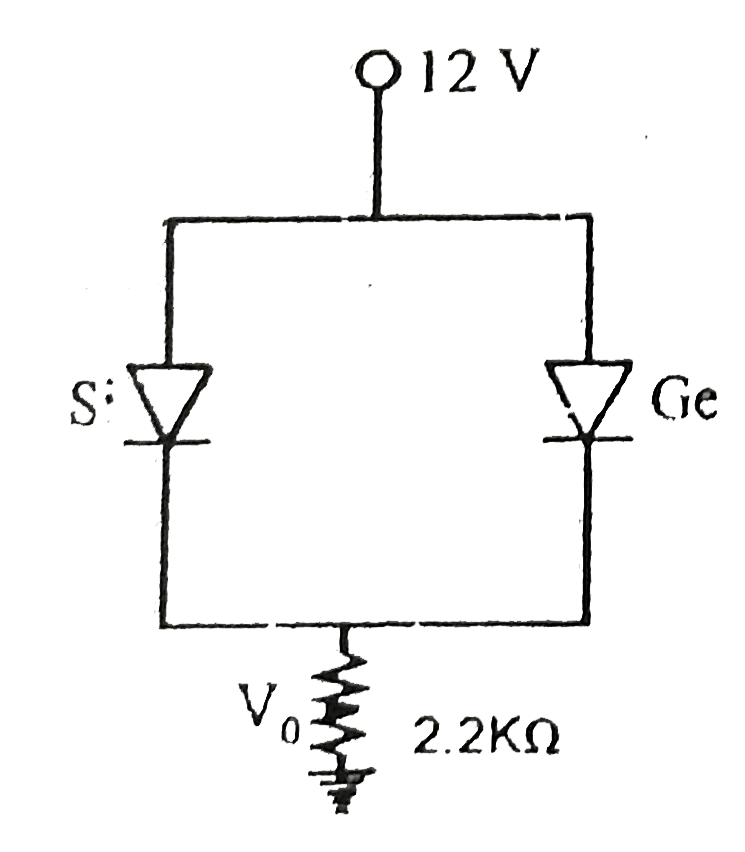 A11.7 voltB11.3 voltC0DNone
 - Question 2 - Select One
In the circuit shown in figure value of VR is
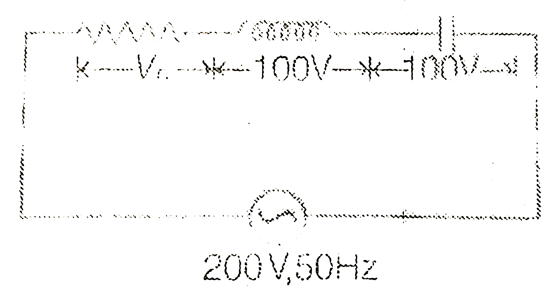 A400VB200VC300VDzero
 - Question 3 - Select One
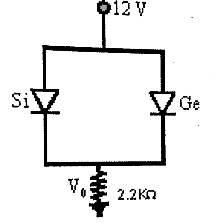
In the circuit shown infigure, voltage V0 is,A11.7 voltB11.3 voltC0DNone of these
Calculate the value of output voltageV0 and I if the Si diode and the Ge diode conduct at 0.7 V and 0.3V respectively, in the circuit given in Fig. If now Ge diode connections are reversed, what will be the new values of V0 and I.
 View Solution
Calculate the value of output voltageV0 and I if the Si diode and the Ge diode conduct at 0.7 V and 0.3V respectively, in the circuit given in Fig. If now Ge diode connections are reversed, what will be the new values of V0 and I.
 View Solution
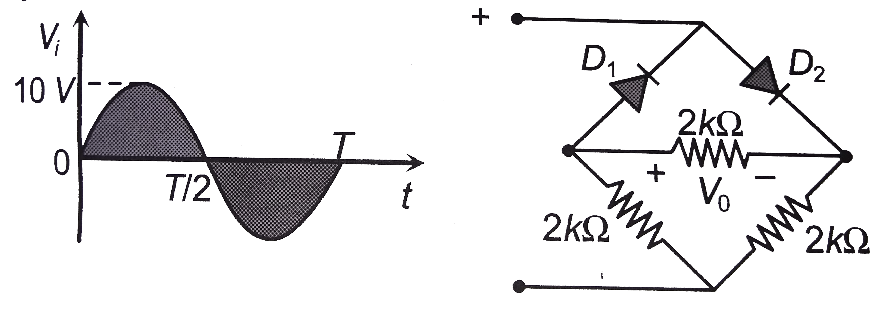
In the circuit shown in figure the maximum output voltage V0 is
 View Solution
Ge and Si diodes conduct at 0.3V and 0.7V respectively. In the following figure if Ge diode connection are reversed, the value of V0 changes by
 View Solution
In the circuit shown in figure, if the diode forward voltage drop is 0.3 V, then the voltage difference between A to B is,
 View Solution


