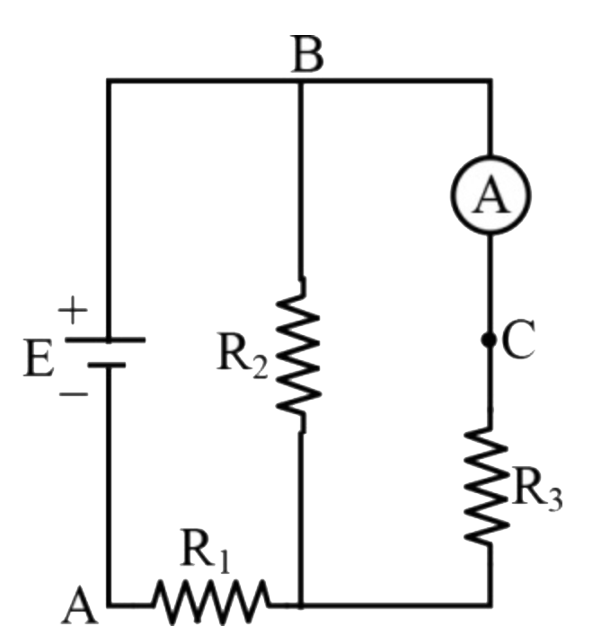
In the circuit shown the ideal ammeter A reads a current of I1 , A . Now the source of e.m.f . and the ammeter are physically interchanged , i.e. . the source is out between B and C and the ammeter between A and B . The ammeter now reads a current of I2 A . Then -
A
I1>I2
B
I1=I2
C
I1<I2
D
The relation between I1andI2 will depend upon the relative value of resistance R1,R2andR3
Text Solution
The correct Answer is:B
|
Topper's Solved these Questions
Similar Questions
Knowledge Check
In the circuit shown, the reading of the ammeter if diode is not ideal, will be
 A0B15mAC>15mAD<15mA
For the circuit shown in fig, the ammeter A2 reads 1.6A and ammeter (A3) reads 0.4A. Then
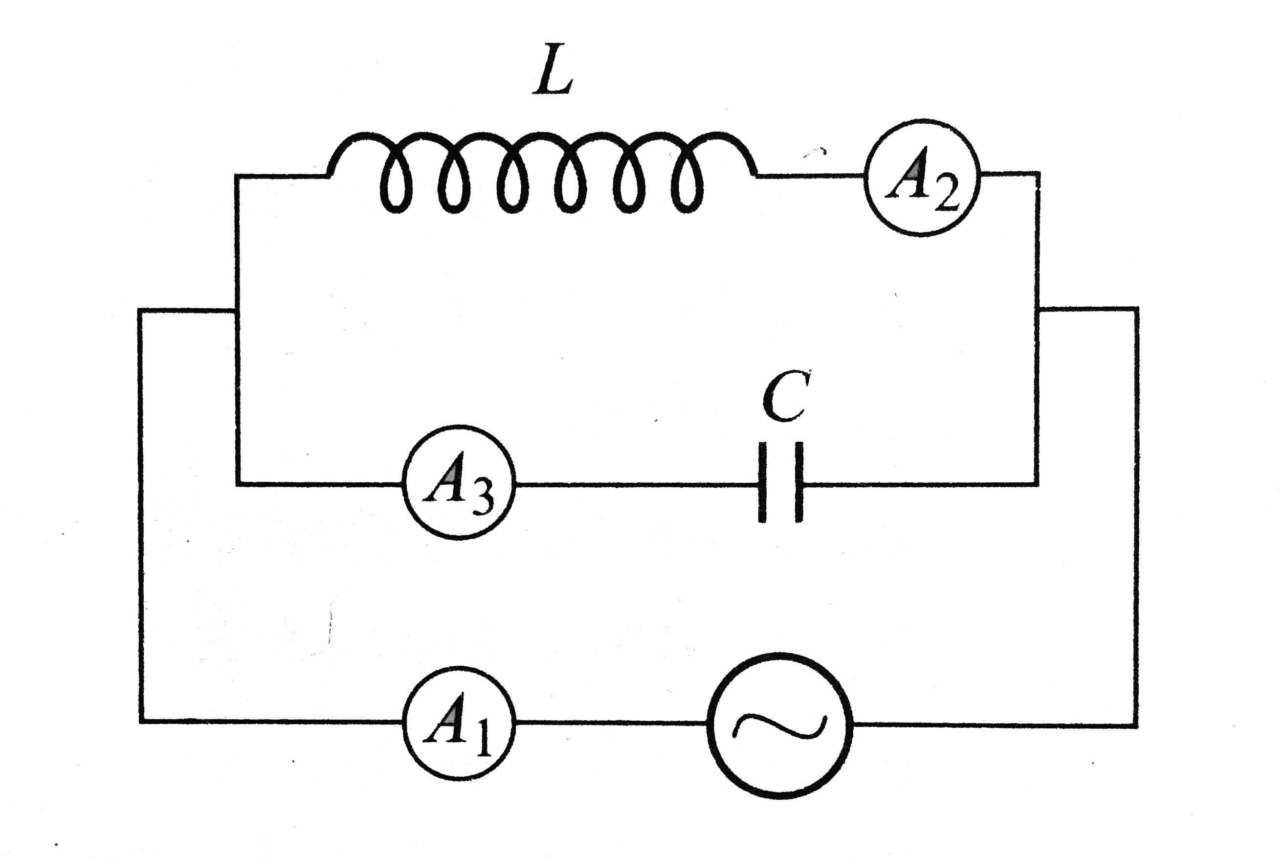 A(A) ω=4√LCB(B)f=2π√LCC(C)The ammeter (A1) reads 1.2 AD(D)the ammeter (A1) reads 2A
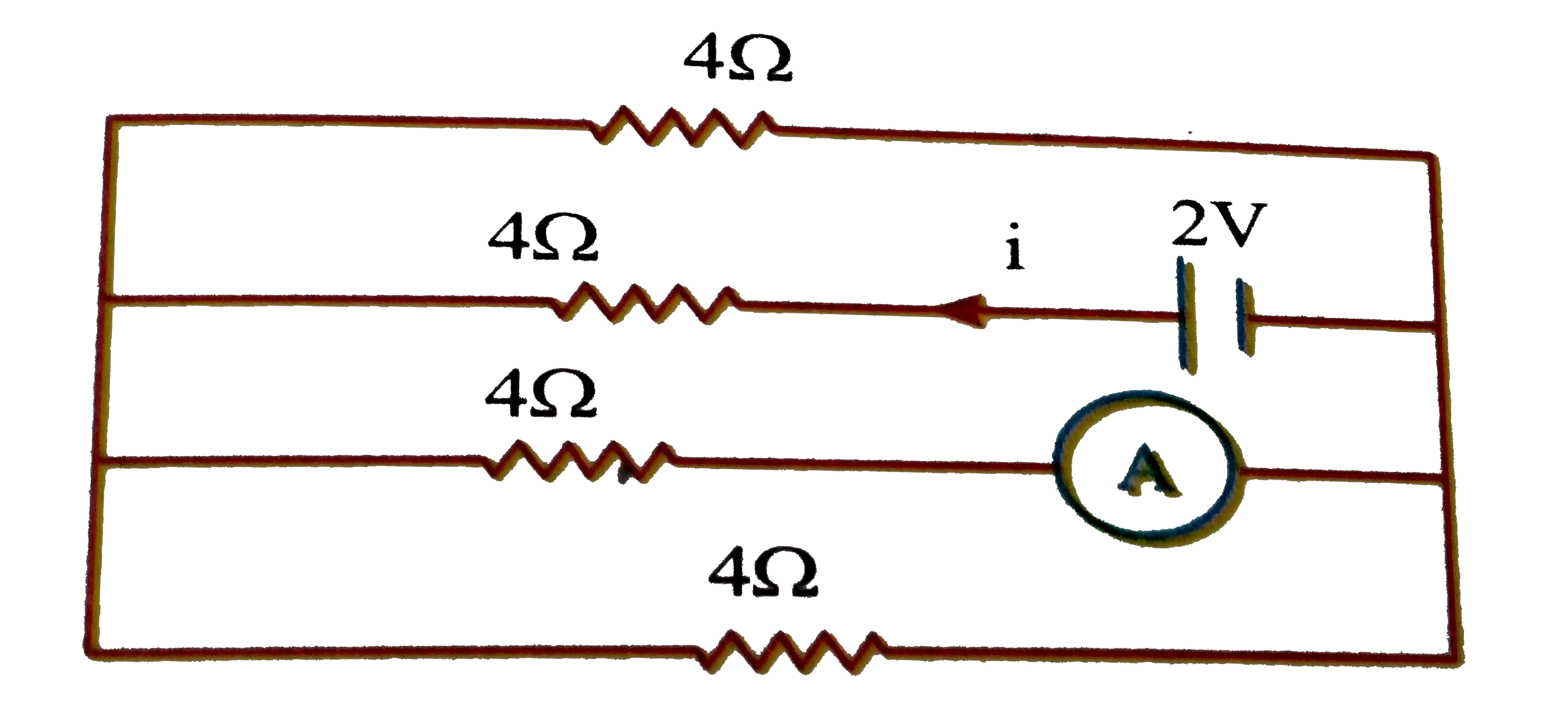
Current i coming from the battery and ammeter reading areA38A,18AB18A,18AC2A,23AD2A,18A
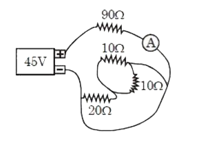
What will the ideal ammeter reading for the circuit shown here ?
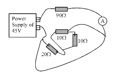
View SolutionFor the circuit shown in fig, the ammeter A2 reads 1.6A and ammeter (A3) reads 0.4A. Then

View SolutionIn the circuit shown, A and V are ideal ammeter and voltmeter respectively. Reading of the voltmeter will be
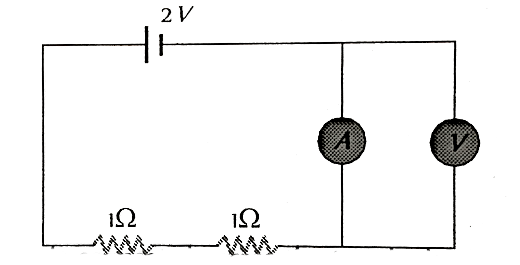
View SolutionIn the circuit shown, A and V are ideal ammeter and voltmeter respectively. Reading of the voltmeter will be

View SolutionIn ac circuit when ac ammeter is connected it reads i current if a student used dc ammeter in place of ac ammeter the reading in the dc ammeter will be:
View Solution

