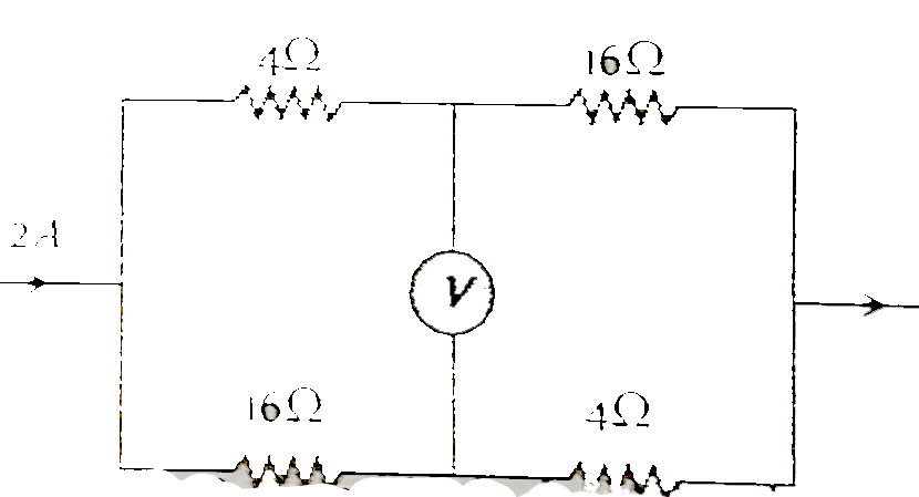
In the circuit shown, A and V are ideal ammeter and voltmeter respectively. Reading of the voltmeter will be
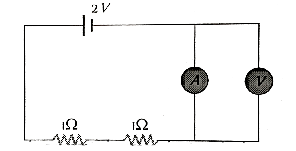
2V
1V
0.5V
Zero
The correct Answer is:D
Step by step video & image solution for In the circuit shown, A and V are ideal ammeter and voltmeter respectively. Reading of the voltmeter will be by Physics experts to help you in doubts & scoring excellent marks in Class 12 exams.
Updated on:21/07/2023Topper's Solved these Questions
- CURRENT ELECTRICITYBOOK - DC PANDEY ENGLISHCHAPTER - CURRENT ELECTRICITYEXERCISE - Taking it together
142 Videos
- CURRENT ELECTRICITYBOOK - DC PANDEY ENGLISHCHAPTER - CURRENT ELECTRICITYEXERCISE - B. Assertion and reason
18 Videos
- CURRENT ELECTRICITYBOOK - DC PANDEY ENGLISHCHAPTER - CURRENT ELECTRICITYEXERCISE - Example
65 Videos
- COMMUNICATION SYSTEMBOOK - DC PANDEY ENGLISHCHAPTER - COMMUNICATION SYSTEMEXERCISE - Subjective
11 Videos
- ELECTROMAGNETIC INDUCTIONBOOK - DC PANDEY ENGLISHCHAPTER - ELECTROMAGNETIC INDUCTIONEXERCISE - Medical entrances gallery
25 Videos
Similar Questions
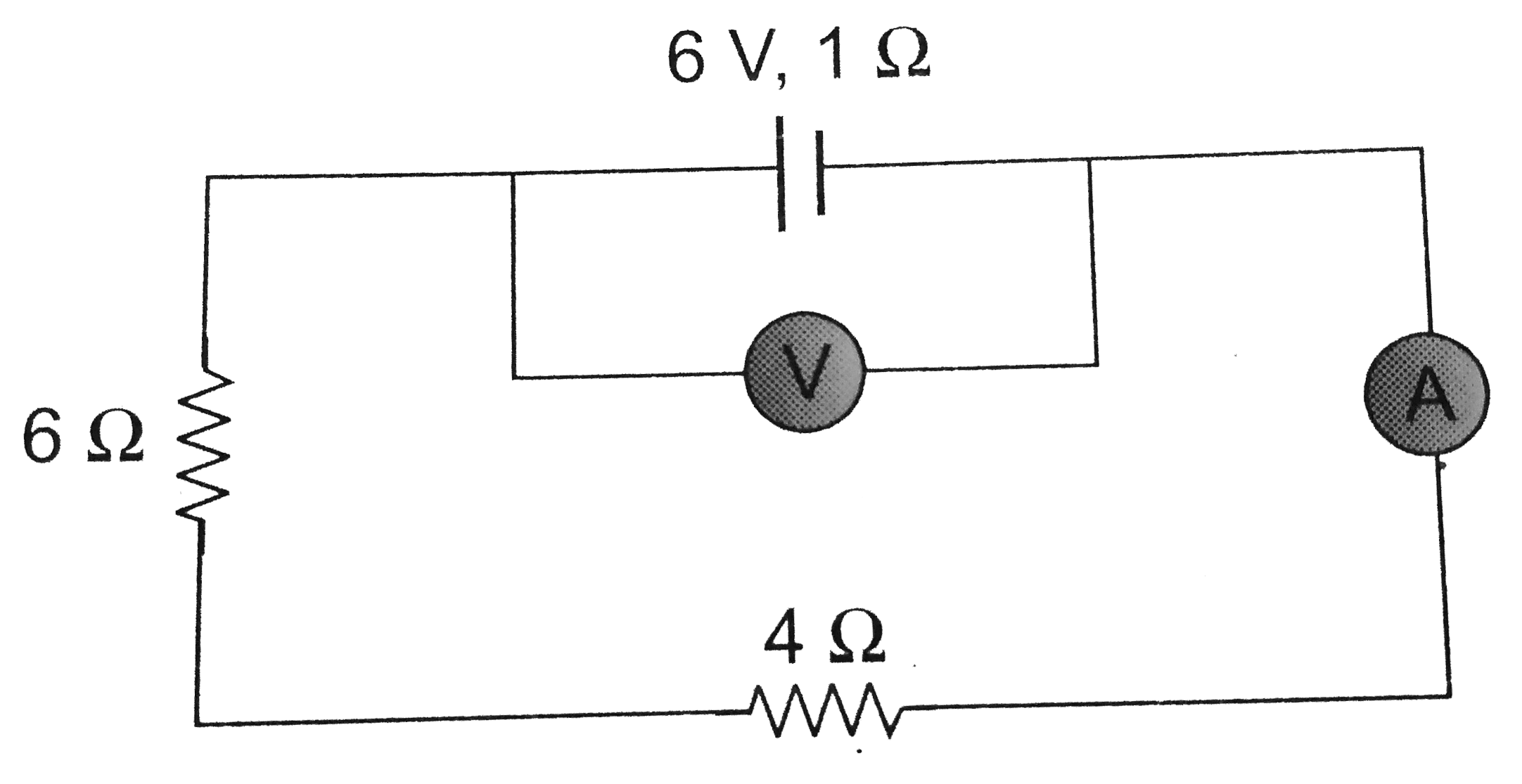
In the circuit shown here, the readings of the ammeter and voltmeter are
View Solution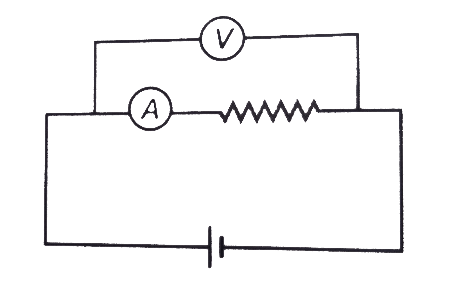
Assertion : In the circuit shown in figure ammeter and voltmeter are non-ideal when positions of ammeter and voltmeter are changed, reading of ammeter will increase while of voltmeter will decrease.
Reason : Resistance of an ideal ammeter is zero while that of an ideal voltmeter is infinite.
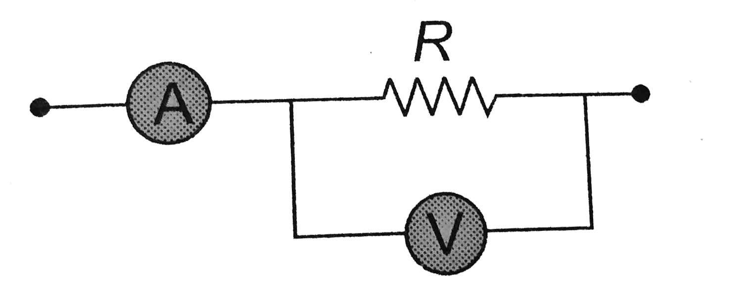
View SolutionIn the circuit shown the reading of ammeter and voltmeter are 4A and 20V respectively. The meters are non ideal, then R ia
View SolutionIn the circuit shown in Fig. 6.50, an idel ammeter and an ideal voltmeter are used. Whan the key is open, the voltmeter reads 1.53V. When the key is closed, the ammeter reads 1.0A and the voltmeter reads 1.03V. The resistance R is
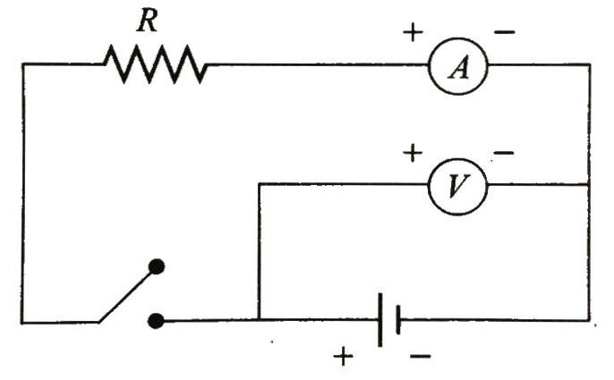
View SolutionIn the circuit shown, the battery, the ammeter and the voltmeter are ideal. Pick the correct choice(s) :
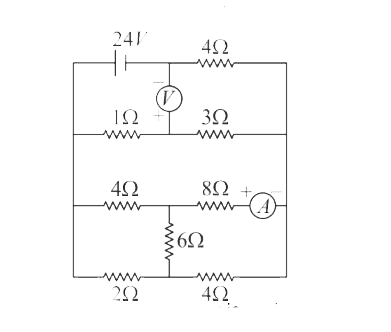
View SolutionIn the circuit shown alongside, the ammeter and the voltmeter redings are 3A and 6V, respectively. Then, the value of the resistance R is

View SolutionIn the circuit shown in the figure, the voltmeter reading is
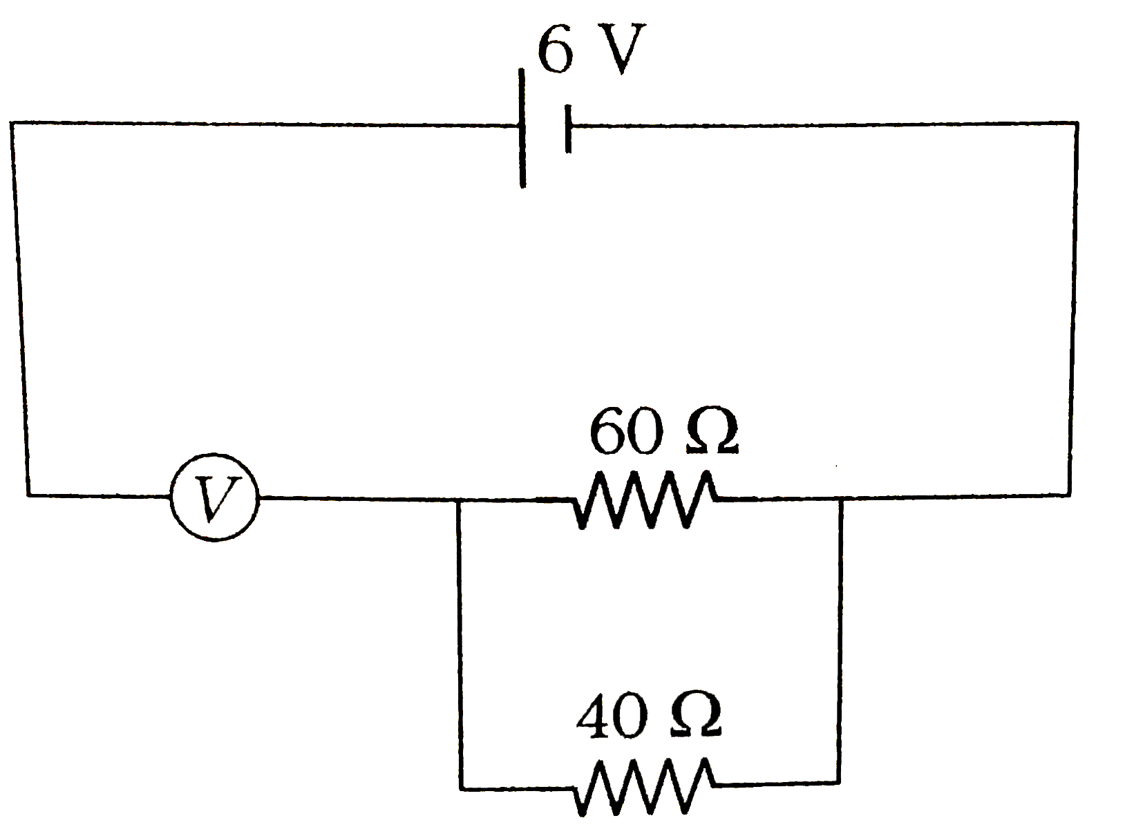
View SolutionIn the circuit shown in figure , if ammeter and voltmeter are ideal , then the power consumed in 9Ω resistor will be .

View SolutionIn the following circuit the reading of the voltmeter will be:-
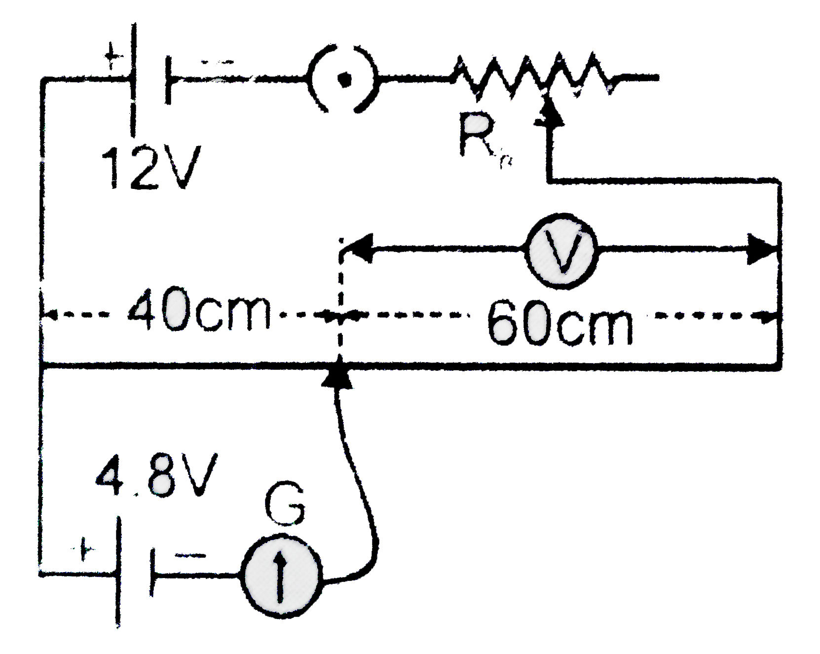
View SolutionIn the circuit shown below. The reading of the voltmeter V is
View Solution
