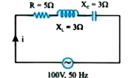
An L.C, R series circuit is connected to ac, source. At resonance, the applied voltage and the current flowing through the circuit will have a phase difference of
π/4
zero
pi
π/2
The correct Answer is:B
To solve the problem of finding the phase difference between the applied voltage and the current flowing through an LCR series circuit at resonance, we can follow these steps:
1. Understanding the Circuit:
- An LCR series circuit consists of an inductor (L), capacitor (C), and resistor (R) connected in series to an AC voltage source.
- At resonance, the inductive reactance (X_L) and capacitive reactance (X_C) are equal.
2. Condition at Resonance:
- At resonance, the condition is given by:
XL=XC
- This implies that the current through the inductor (I_L) and the current through the capacitor (I_C) are equal in magnitude but opposite in phase.
3. Current in the Circuit:
- The current through the resistor (I_R) is in phase with the applied voltage (V).
- Since I_L and I_C are equal and opposite, they effectively cancel each other out at resonance.
4. Net Current:
- The net current (I) in the circuit is the same as the current through the resistor (I_R) because the effects of I_L and I_C cancel each other out.
- Therefore, the net current is in phase with the applied voltage.
5. Phase Difference:
- Since the net current (I) is in phase with the applied voltage (V), the phase difference between the applied voltage and the current flowing through the circuit at resonance is:
Phase Difference=0∘
Conclusion:
At resonance in an LCR series circuit, the phase difference between the applied voltage and the current flowing through the circuit is 0 degrees.
- An LCR series circuit consists of an inductor (L), capacitor (C), and resistor (R) connected in series to an AC voltage source.
- At resonance, the inductive reactance (X_L) and capacitive reactance (X_C) are equal.
- At resonance, the condition is given by:
XL=XC
- This implies that the current through the inductor (I_L) and the current through the capacitor (I_C) are equal in magnitude but opposite in phase.
- The current through the resistor (I_R) is in phase with the applied voltage (V).
- Since I_L and I_C are equal and opposite, they effectively cancel each other out at resonance.
- The net current (I) in the circuit is the same as the current through the resistor (I_R) because the effects of I_L and I_C cancel each other out.
- Therefore, the net current is in phase with the applied voltage.
- Since the net current (I) is in phase with the applied voltage (V), the phase difference between the applied voltage and the current flowing through the circuit at resonance is:
Phase Difference=0∘
At resonance in an LCR series circuit, the phase difference between the applied voltage and the current flowing through the circuit is 0 degrees.
Topper's Solved these Questions
- BOOK - FIITJEECHAPTER - AC CIRCUITSEXERCISE - ASSIGNMENT PROBLEMS(OBJECTIVE Level - Il)1videos
AC CIRCUITS
- BOOK - FIITJEECHAPTER - AC CIRCUITSEXERCISE - ASSIGNMENT PROBLEMS(OBJECTIVELevel - Il)14videos
AC CIRCUITS
- BOOK - FIITJEECHAPTER - AC CIRCUITSEXERCISE - ASSIGNMENT PROBLEMS (SUBJECTIVE)(leve II)15videos
AC CIRCUITS
- BOOK - FIITJEECHAPTER - COLLISION EXERCISE - (NUMERICAL BASED QUESTIONS)4videos
COLLISION
Similar Questions
A capacitor only is connected to an AC source. What will be the phase difference between the current flowing in the circuit and the potential difference between the plates of the capacitor?
View Solution(a) An AC source of voltage V=V0sinωt is connected across a series combination of an inductor a capacitor and a resistor . Use the phasor diagram to obtain the expression for the impedance of the circuit and phase angle between the voltage and the current.
(b) A capacitor of unknown capacitance a resistor of 100 Ω and an inductor of self - inductance L =(4/π2) henry are in series connected to an AC source of 200 V and 50 Hz . Calculate the value of the capacitance and the current that flows in the circuit when the current is in phase with the voltage .View Solution
Knowledge Check
- Question 1 - Select One
An LCR circuit is connected to a source of alternating current. At resonance, the applied voltage and the current flowing through the circuit will have a phase difference of
Aπ/4BzeroCπDπ/2 - Question 2 - Select One
An L-C-R series circuit , connected to a source E, is at resonance. Then,
Athe voltage across R is zeroBthe voltage across R equals applied voltageCthe volatage across C is zeroDthe voltage across C equals applied voltage - Question 3 - Select One
An L-C-R circuit is connected to a source of A.C. current. At resonance, the phase difference between the applied voltage and the current in the circuit, is
AπBZeroCπ4Dπ2
A series L-C-R circuit is given in figure . The current through the circuit is
 View Solution
In a LCR series circuit, if the phase difference between applied voltage and current is zero then
View SolutionIn a series L, R, C, circuit which is connected to a.c. source. When resonance is obtained then net impedance Z will be
View SolutionIn an L-C-R series, AC circuit at resonance
View SolutionThe phase difference between voltage and current in series L-C circuit is
View Solution

