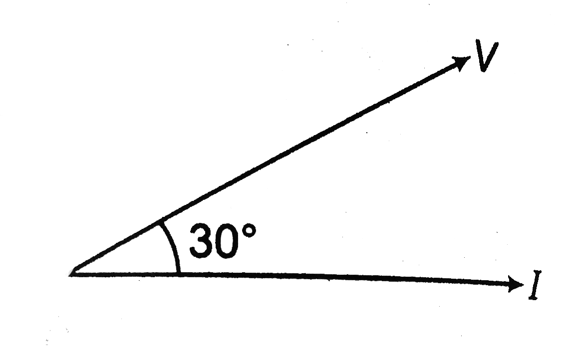
Series AC Circuit | Phasor Diagram
Video Solution
|
Answer
Step by step video solution for Series AC Circuit | Phasor Diagram by Physics experts to help you in doubts & scoring excellent marks in Class 12 exams.
Updated on:21/07/2023Similar Questions
Knowledge Check
Phasor diagram of a series AC circuit is shown in figure. Then,
 AThe circuit must be containing resistor and capacitor onlyBThe circuit must be containing resistor and inductor onlyCThe circuit must be containing all three elements L, C and RDThe circuit cannot have only capacitor and inductor
A series AC circuit has a resistance of 4Ω and a reactance of 3Ω. The impedance of the circuit is
A5ΩB7ΩC12/7ΩD7/12ΩFor a RLC series circuit , phasors of current i and applied voltage V=V0sinωt are shown in diagram at t=0, which of the following is/are CORRECT?
AAt =π2ω, instantaneous power supplied by source is negative.BFrom 0<t<2π3ω, average power supplied by source is positive.CAt t=5π6ω, instantaneous power supplied by source is negative.DIf ω is increased slightly, angle between the two phasors decreases.
Questions|R-L-C Series AC Circuit|Resonance|OMR
View SolutionQuestions|Reflection Of A Plane Wave By A Plane Surface|Analysis Of Interference Of Light|Phasor Diagram|Types Of Interference|Questions|OMR
View SolutionPhasor Diagram|Purely - R - AC Circuit|R-L Series AC Circuit|R-C Circuit|Power In AC Circuit|OMR
View SolutionWhat is a phasor ? What is its use in a.c. circuit ? Draw a phasor diagram for pure resistive a.c. circuit.
View SolutionPhasor Diagrams impedence | Phase factor & power factor | Resonance in series LCR circuit | Parallel R-C | R-L | LCR circuits
View Solution
