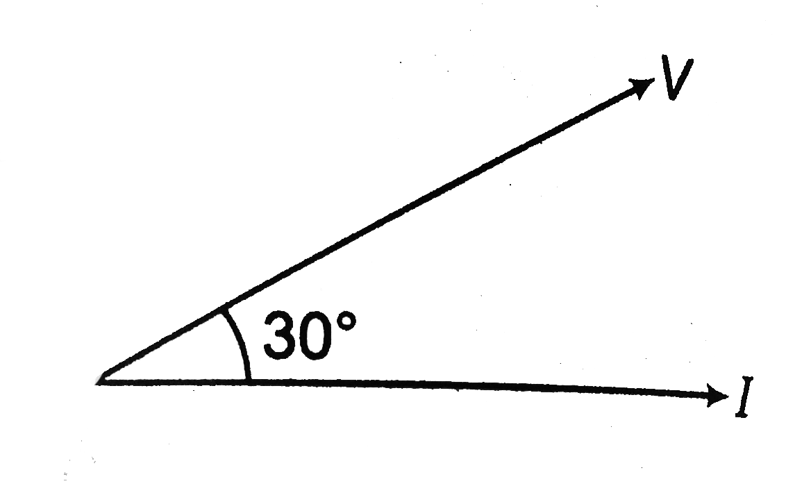
Phasor diagram of a series AC circuit is shown in figure. Then,
A
The circuit must be containing resistor and capacitor only
B
The circuit must be containing resistor and inductor only
C
The circuit must be containing all three elements L, C and R
D
The circuit cannot have only capacitor and inductor
Video Solution
Text Solution
The correct Answer is:D
In case of only capacitor and inductor phase difference between current and voltage should be 90∘
|
Topper's Solved these Questions
- ALTERNATING CURRENTBOOK - DC PANDEYCHAPTER - ALTERNATING CURRENTEXERCISE - Level - 1 Subjective
6 Videos
- ALTERNATING CURRENTBOOK - DC PANDEYCHAPTER - ALTERNATING CURRENTEXERCISE - Level- 2 Single Correct
18 Videos
- ALTERNATING CURRENTBOOK - DC PANDEYCHAPTER - ALTERNATING CURRENTEXERCISE - Level 1 Assertion-Reason
11 Videos
- ATOMSBOOK - DC PANDEYCHAPTER - ATOMSEXERCISE - MEDICAL ENTRANCES GALLERY
42 Videos
Similar Questions
Knowledge Check
Phasor diagram of a series AC circuit is shown in figure. Then,
 AThe circuit must be containing resistor and capacitor onlyBThe circuit must be containing resistor and inductor onlyCThe circuit must be containing all three elements L, C and RDThe circuit cannot have only capacitor and inductor
In the circuit shown in figure
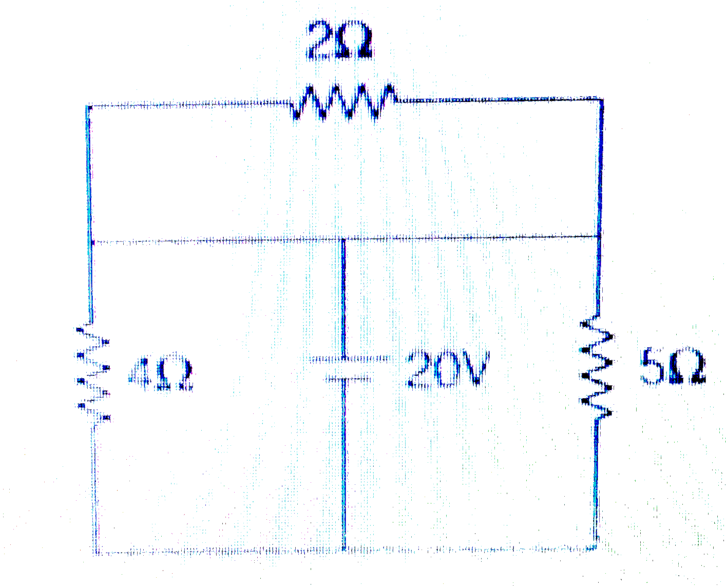 Acurrent passing through 2Ω resistance is zeroBcurrent passing through 4Ω resistance is 5 ACcurrent passing through 5Ω resistance is 4 ADAll of the above
In the circuit shown in figure
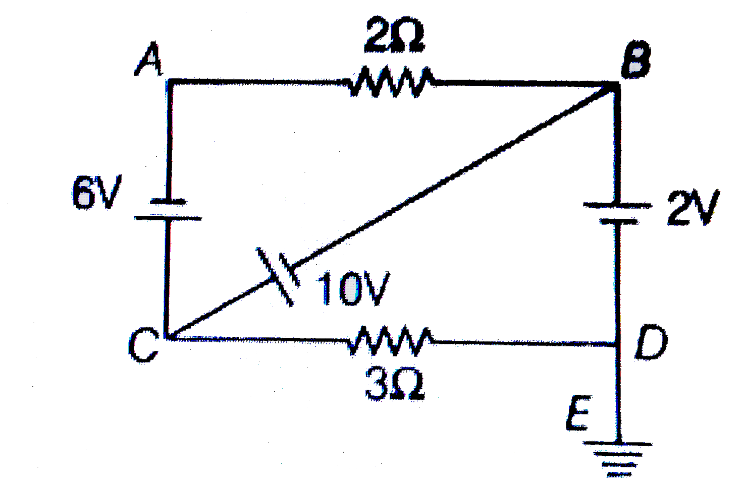 Acurrent passing through 2Ω resistance is 2 ABcurrent passing through 3Ω resistance is 4 ACcurrent in wire DE is zero.Dpotential of point A is 10 V
The schematic diagram of an open circuit is shown in the given figure.

Which of the following objects is inserted tightly in the gap to make the bulb glow?
View SolutionDraw the phasor diagram for a series RC circuit connected to an a.c. source.
View SolutionIn the circuit shown in figure
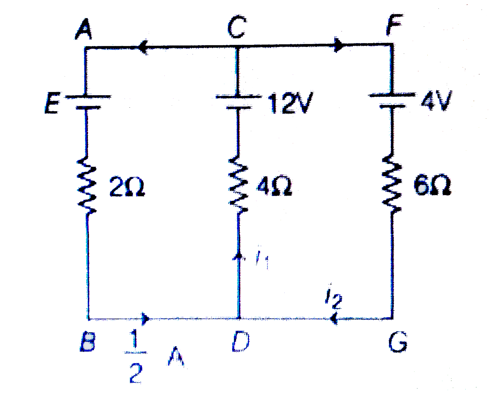
View SolutionIn L−C−R series AC circuit,
View SolutionThe vector diagram of the current and voltage in a given circuit is shown in the figure. The components of the circuit will be -
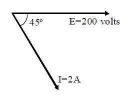
View Solution

