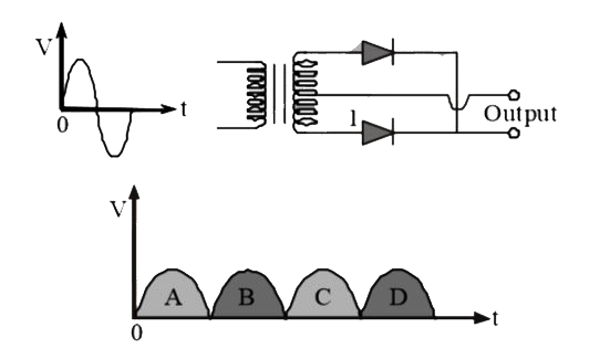
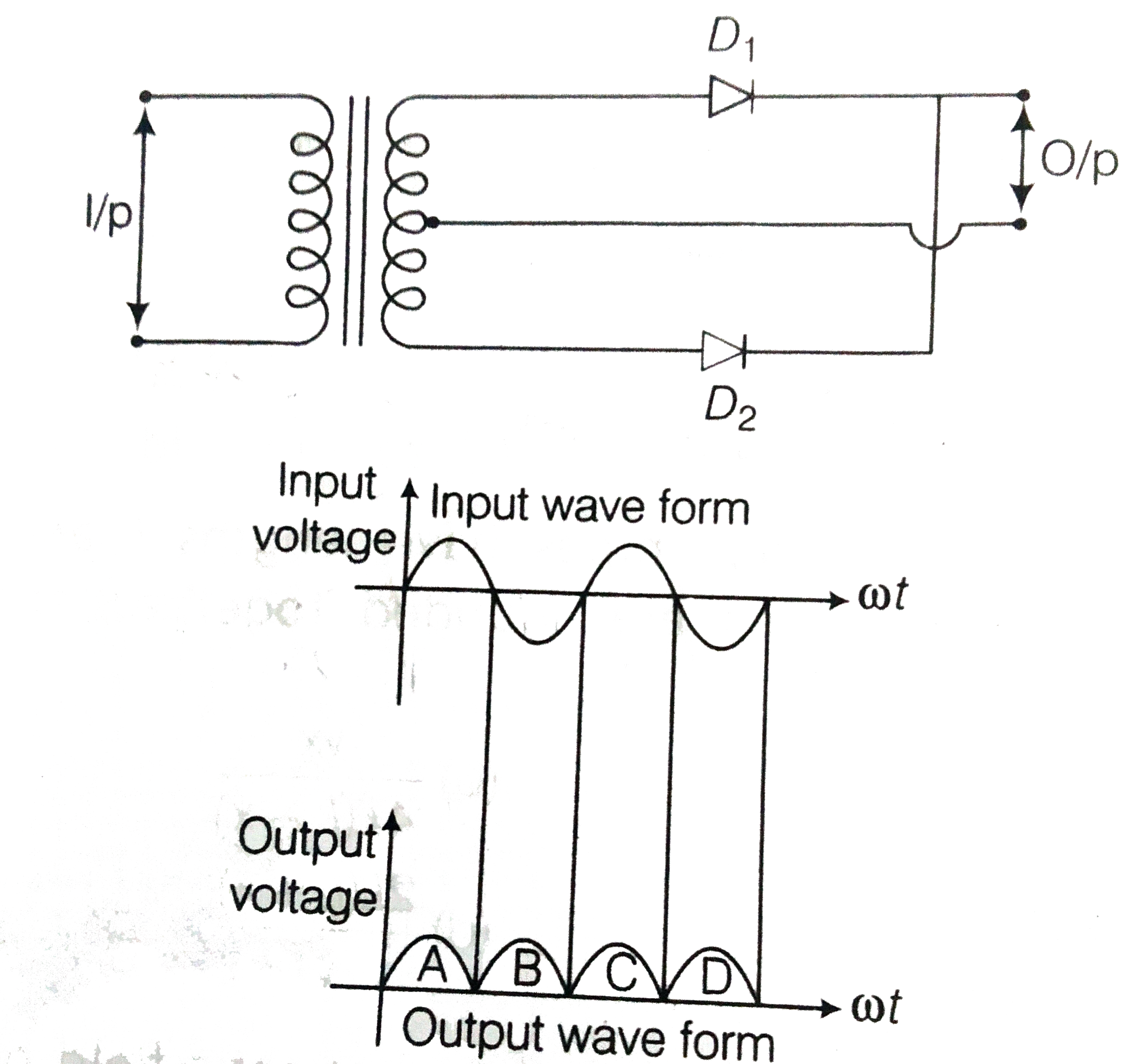
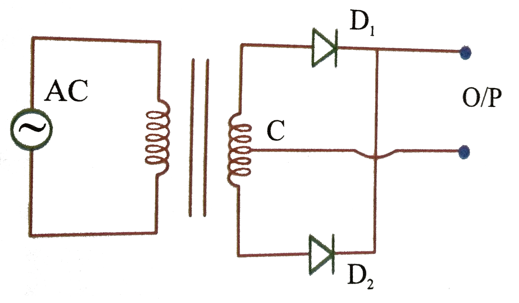
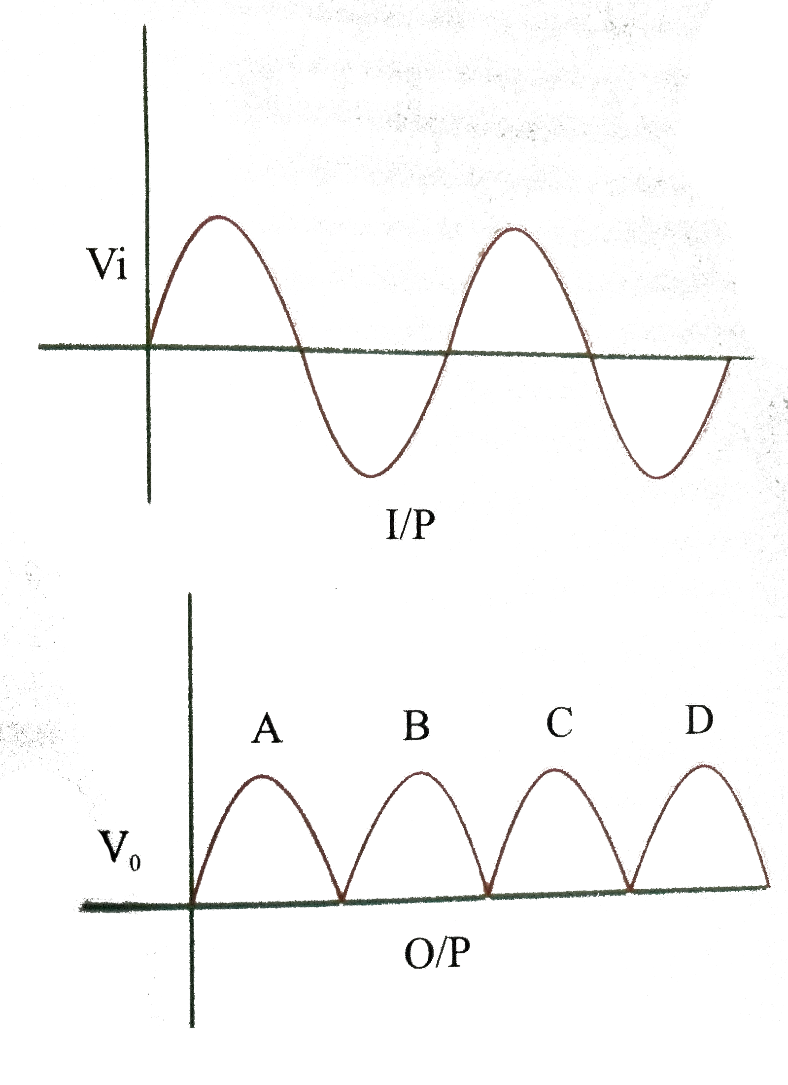
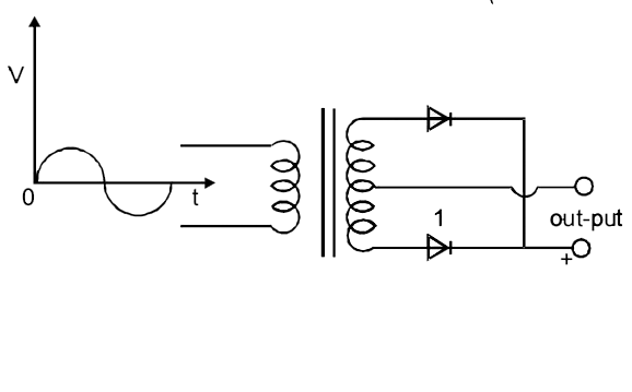
A full wave rectifier with the output is shown in fig. the contributions from the diode (2) are.
 .
.
C
A,C
B,D
A,B,C,D
The correct Answer is:C
Step by step video, text & image solution for A full wave rectifier with the output is shown in fig. the contributions from the diode (2) are. . by Physics experts to help you in doubts & scoring excellent marks in Class 12 exams.
Updated on:21/07/2023Topper's Solved these Questions
- SEMICONDUCTOR ELECTRONICSBOOK - NARAYNACHAPTER - SEMICONDUCTOR ELECTRONICSEXERCISE - C.U.Q (SPECIAL PURPOSE P-N JUNCTION DIODES)
51 Videos
- SEMICONDUCTOR ELECTRONICSBOOK - NARAYNACHAPTER - SEMICONDUCTOR ELECTRONICSEXERCISE - C.U.Q (LOGIC GATES)
21 Videos
- SEMICONDUCTOR ELECTRONICSBOOK - NARAYNACHAPTER - SEMICONDUCTOR ELECTRONICSEXERCISE - C.U.Q (INTRINSIC AND EXTRINSIC SEMICONDUCTORS)
70 Videos
- SEMI CONDUCTOR DEVICESBOOK - NARAYNACHAPTER - SEMI CONDUCTOR DEVICESEXERCISE - Level-II (H.W)
36 Videos
- WAVE OPTICSBOOK - NARAYNACHAPTER - WAVE OPTICSEXERCISE - Exercise - 4 Polarisation
9 Videos
Similar Questions
Knowledge Check
A full - wave rectifier circult along the out - put is shown in figure . The contribution (s) from the diode 1 is are
 .
.
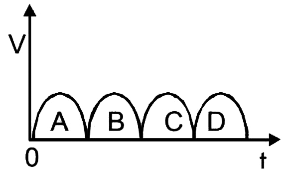 ACBA,CCB,DDA,B,C,D
A full wave rectifier circuit along with the input and output are shown in Fig. the concentrations from the diode I is (are)
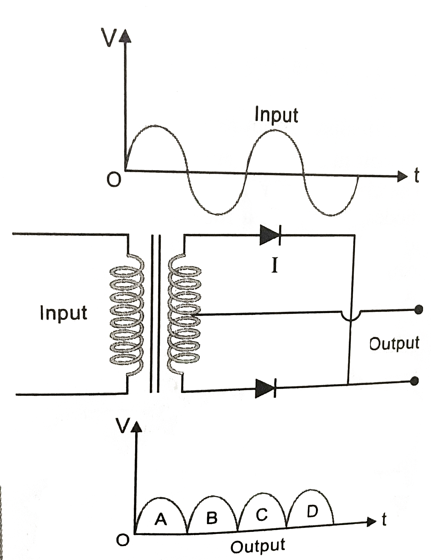 ACBA, CCB, DDA, B, C, D
A full wave rectifier circuit along with the input and output voltages is shown in the figure
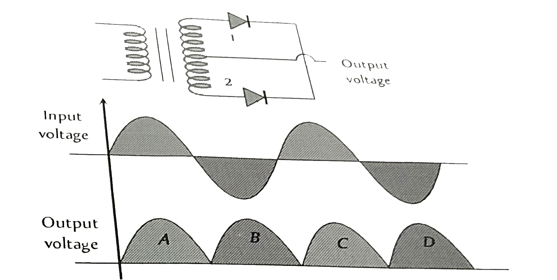
The contribution to output voltage from diode – 2 isAA,CBB,DCB,CDA,D
In a a .c. input signal, of frequency 60 Hz, is rectified by a (i) half wave, (ii) full wave rectifier. Draw the output wave from and write the output frequency in each case.
View SolutionConsider a silicon diode with a threshold voltage of −0.7V, used as a half wave rectifier. Draw the output if the input is a sine wave from of amplitude 2V and circuit is on in reverse position.
View SolutionThe rms value of input voltage in a full wave rectifier is 12 V determine the output voltage if a step up a transformer with ratio 1:2 is used
View SolutionThe circuit used to change alternating voltage to direct voltage is called rectifier
(a) with a neat diagram explain the working of a full wave rectifier having two diodes
(b) what is the output frequency of a full wave rectifier if the input frequency is 50 Hz
(c ) Draw the output waveform across the load resistance connected in the full wave rectifier circuit
View SolutionIn a full wave rectifier if input freq, is 50 Hz then output nipple frequency will be :-
View Solution

