The output of the given circuit in Fig.
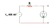
A
would be zero at all times
B
would be like a half-wave recifier with positive cycles in output
C
would be like a half-wave rectifer with negative cycles in output
D
would be like that of a full-wave rectifier.
Video Solution
Text Solution
The correct Answer is:C
|
Answer
Step by step video, text & image solution for The output of the given circuit in Fig. by Physics experts to help you in doubts & scoring excellent marks in Class 12 exams.
Updated on:21/07/2023Topper's Solved these Questions
- SEMICONDUCTOR ELECTRONICSBOOK - NARAYNACHAPTER - SEMICONDUCTOR ELECTRONICSEXERCISE - C.U.Q (SPECIAL PURPOSE P-N JUNCTION DIODES)
51 Videos
- SEMICONDUCTOR ELECTRONICSBOOK - NARAYNACHAPTER - SEMICONDUCTOR ELECTRONICSEXERCISE - C.U.Q (LOGIC GATES)
21 Videos
- SEMICONDUCTOR ELECTRONICSBOOK - NARAYNACHAPTER - SEMICONDUCTOR ELECTRONICSEXERCISE - C.U.Q (INTRINSIC AND EXTRINSIC SEMICONDUCTORS)
70 Videos
- SEMI CONDUCTOR DEVICESBOOK - NARAYNACHAPTER - SEMI CONDUCTOR DEVICESEXERCISE - Level-II (H.W)
36 Videos
- WAVE OPTICSBOOK - NARAYNACHAPTER - WAVE OPTICSEXERCISE - Exercise - 4 Polarisation
9 Videos
Similar Questions
Knowledge Check
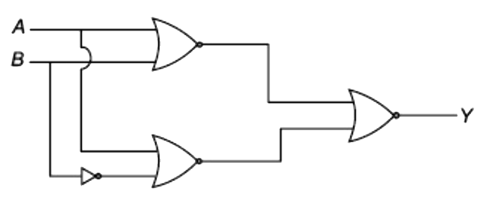
The output for the given, circuit is
 A(A+B)⋅¯¯¯BB(A⋅B)⋅¯¯¯BC(A+B)⋅BD(A⋅B)⋅B
If the given diode is ideal, the output of the given circuit in
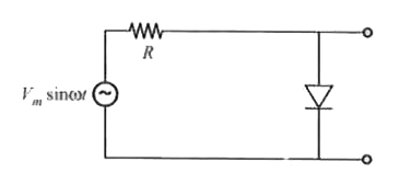 Awould be zero at all times.Bwould be like a half wave rectifier with positive cycles in output.Cwould be like a half wave rectifier with negative cycles in output.Dwould be like that of a full wave rectifier.
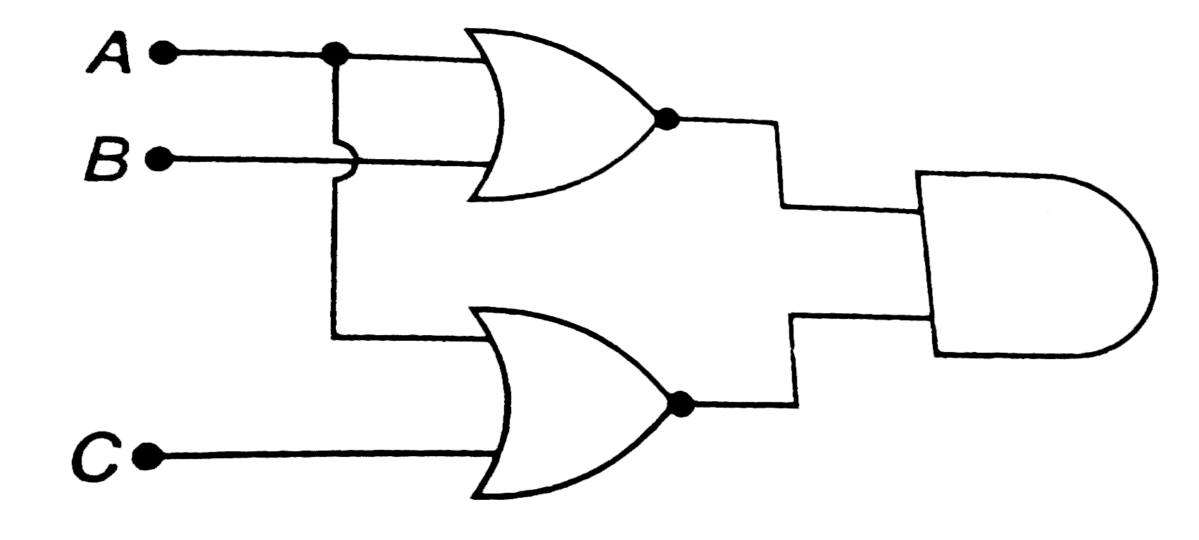
The output of given logic circuit is
 AA⋅(B+C)BA⋅(B⋅C)C(A+B)⋅(A+C)DA+B+C
The output of given logic circuit is
View SolutionWhich one of the following will be the output of the given circuit?

View SolutionThe output of the following circuit is
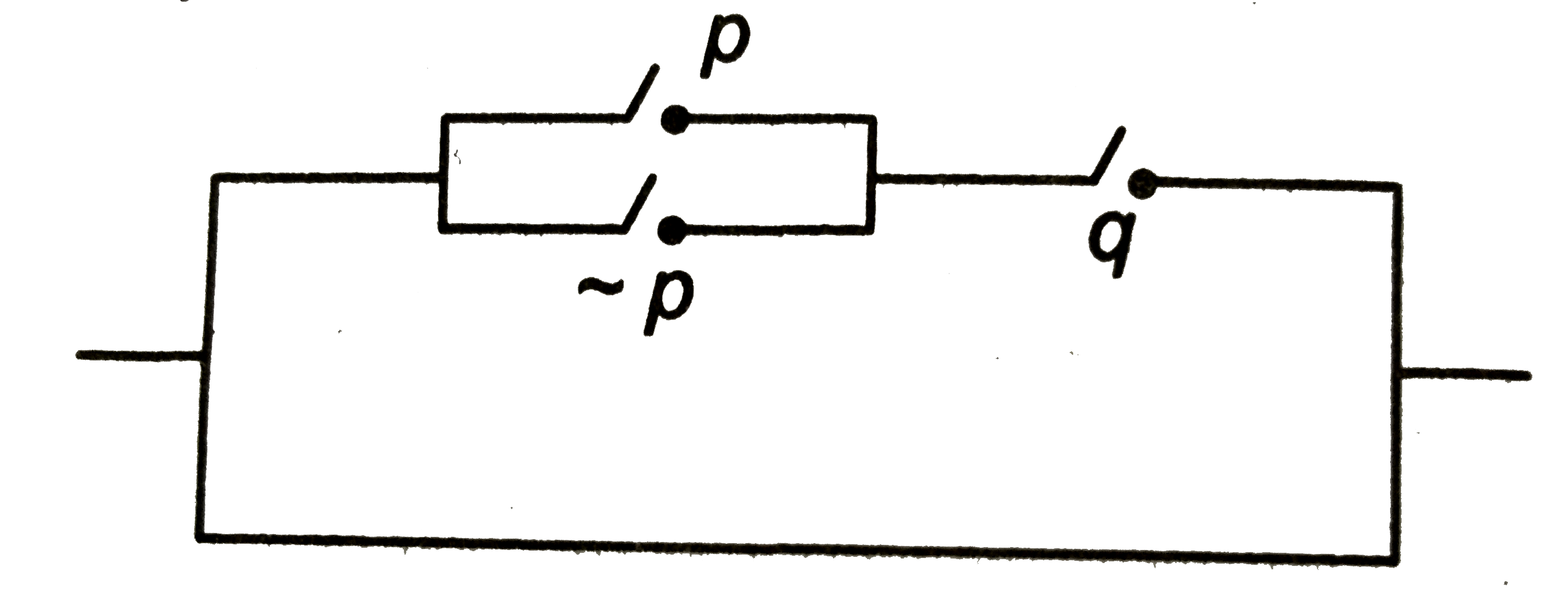
View SolutionThe output of the given logic circuit is :
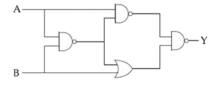
View SolutionThe output Y of the gate circuit shown in the figure below is

View Solution

