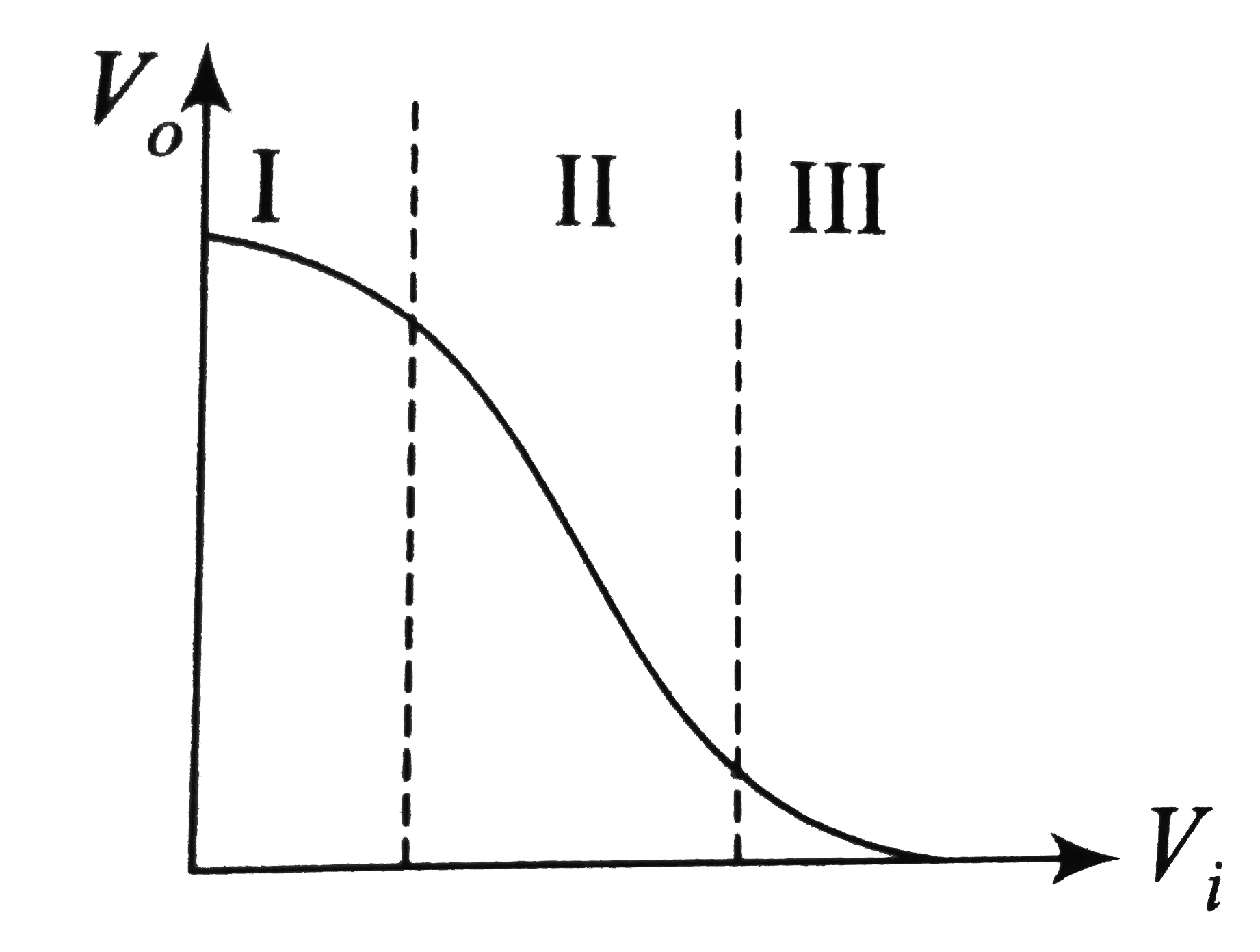
Figure shows the transfer characteristics of a base biased CE transistor. Which of the following statements are true ?
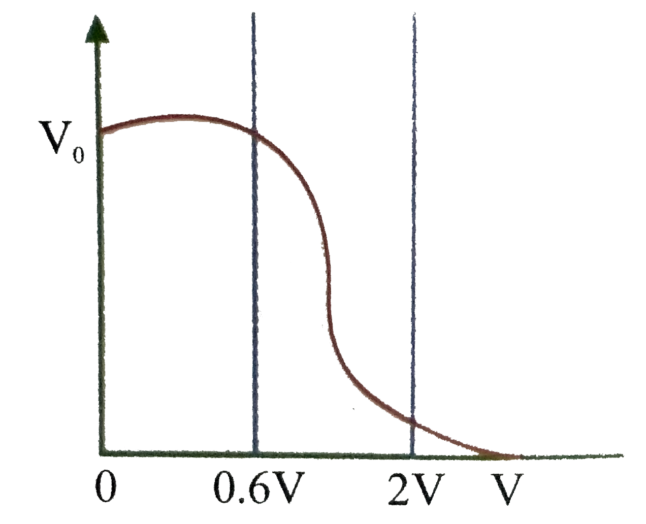
(A) At V1=0.14V transistors is in active state
(B) At V1=1V it can be used as an amplifier
(C) At V1=0.5V, it can be used as a switch turned off
(D) At V1=2.5V, it can be used as switch turned on
A, B, C
B, C, D
A, C, D
A, B, D
The correct Answer is:B
From the given transfer characteristics of a base biased common emitter transsistor, we note that (ii) When V1=1V (which is in between 0.6V to 2.V), the transistor circuit is in active state and it used as an amplifier
(iii) When V1=0.5V there is no collector current, The transistor is in cut off state. The transistor cirucit can be used as a switch turned off
(iv) When V1=2.5V the colloctor current becomes maximum and transistor is in saturation and can be used as switch turned on statc
Topper's Solved these Questions
- SEMICONDUCTOR ELECTRONICSBOOK - NARAYNACHAPTER - SEMICONDUCTOR ELECTRONICSEXERCISE - EXERCISE -2 (H.W) (LOGIC GATE)
6 Videos
- SEMICONDUCTOR ELECTRONICSBOOK - NARAYNACHAPTER - SEMICONDUCTOR ELECTRONICSEXERCISE - EXERCISE -3
43 Videos
- SEMICONDUCTOR ELECTRONICSBOOK - NARAYNACHAPTER - SEMICONDUCTOR ELECTRONICSEXERCISE - EXERCISE -2 (H.W) (APPLICATIONS OF JUNCTION DIODE AS RECTIFIER)
4 Videos
- SEMI CONDUCTOR DEVICESBOOK - NARAYNACHAPTER - SEMI CONDUCTOR DEVICESEXERCISE - Level-II (H.W)
36 Videos
- WAVE OPTICSBOOK - NARAYNACHAPTER - WAVE OPTICSEXERCISE - Exercise - 4 Polarisation
9 Videos
Similar Questions
Draw the transfer characteristic curve of a base biased transistor in CE configuration. Explain clearly how the active region of the Vo versus Vi curve in a transistor is used as an amplifier.
View SolutionDraw the tramsfer characteristic curve of a base biased transistor in CE configuration. Explain clearly how the active region of the Vo versus Vi curve in a transistor is used as an amplifier.
View Solution
Knowledge Check
In the following diagram if V2>V1 then
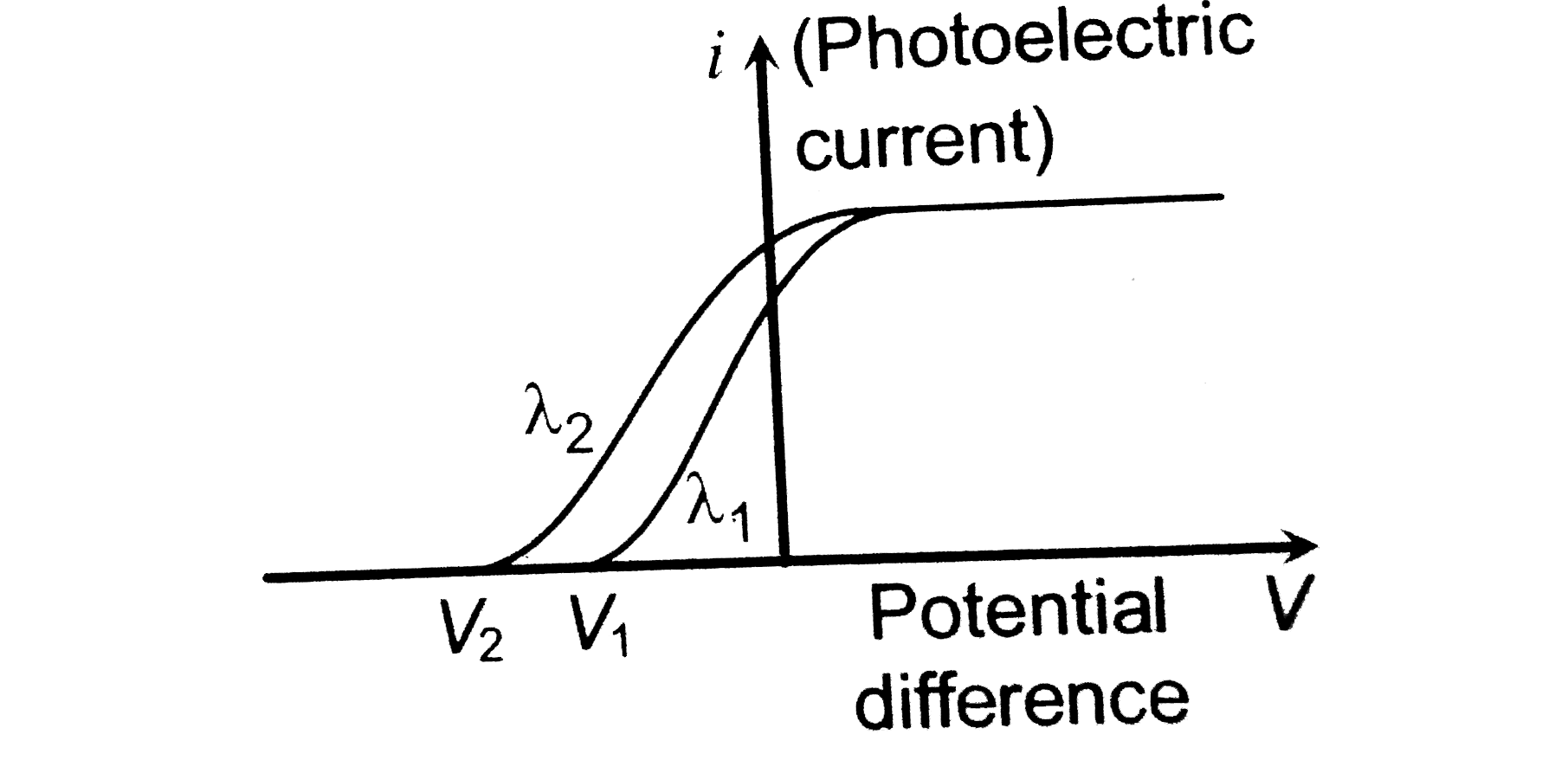 Aλ1=√λ2Bλ1<λ2Cλ1=λ2Dλ1>λ2
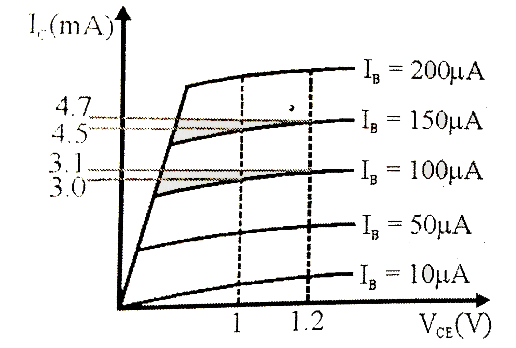
Output characteristic of n-p-n transistor in CE configuration is shown. From the characteristic curve determine the current gain at VCE=1V-A30B32C28D40What is the base resistance RB in the circuit as shown in figure , if βd.c.=90,VBE=0.7V,VCE=4V?
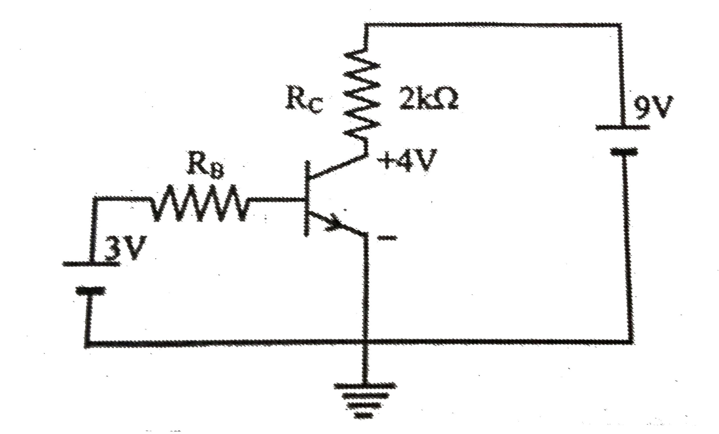 A29KΩB82KΩC108KΩD55KΩ
The output characteristics of a transistor is shown in the figure. When VCE is 10 V and IC=4.0mA, then value of βac is _________
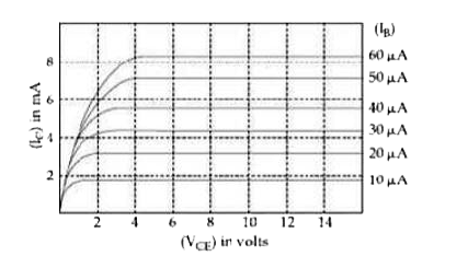
View SolutionFrom the output characteristic shown in fig. calculate the value of current amplification factor of the transistor when VCE=2V.
View SolutionTwo batteries V1 and V2 are connected to three resistors as shown below. If V1=2Vand V2 = 0 V, the current I = 3 mA. If V1 = 0 V and V2 = 4V, the current I = 4mA. Now, if V1 = 10 V and V2 = 10 V, the current I will be-

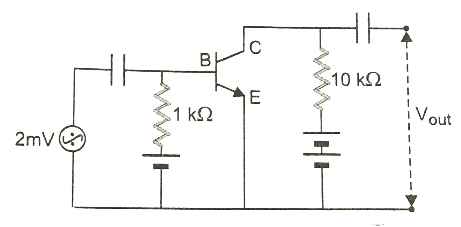
View SolutionIn the common emitter amplifier circuit, Fig. an npn transistor with output voltage of the amplifier as 1 V, the current gain of transistor amplifier is :
View SolutionTransfer characterstics [output voltage (Vo) vs. input voltage (Vi)] for a base biased transistor in CE configuration is as shown in the figure. For using transfor as a which, it is used
View Solution
