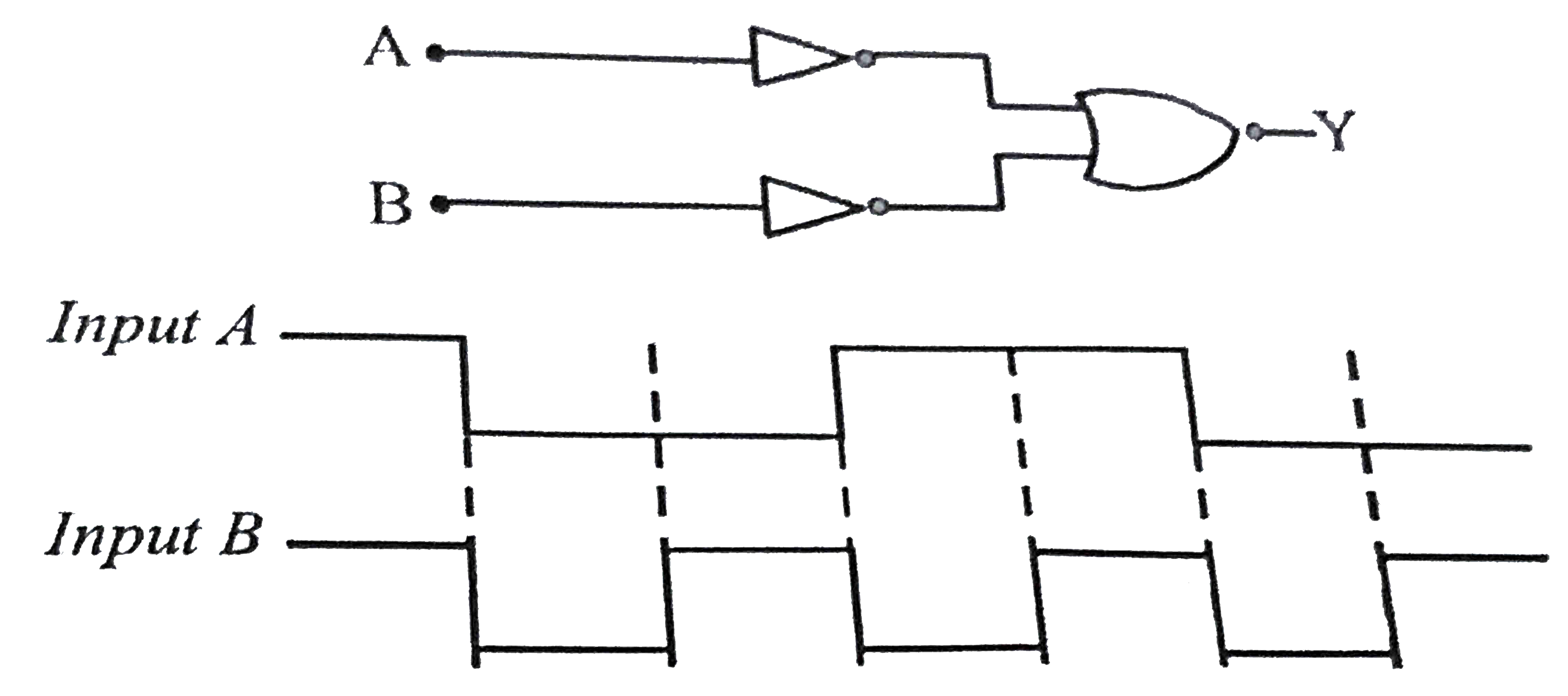
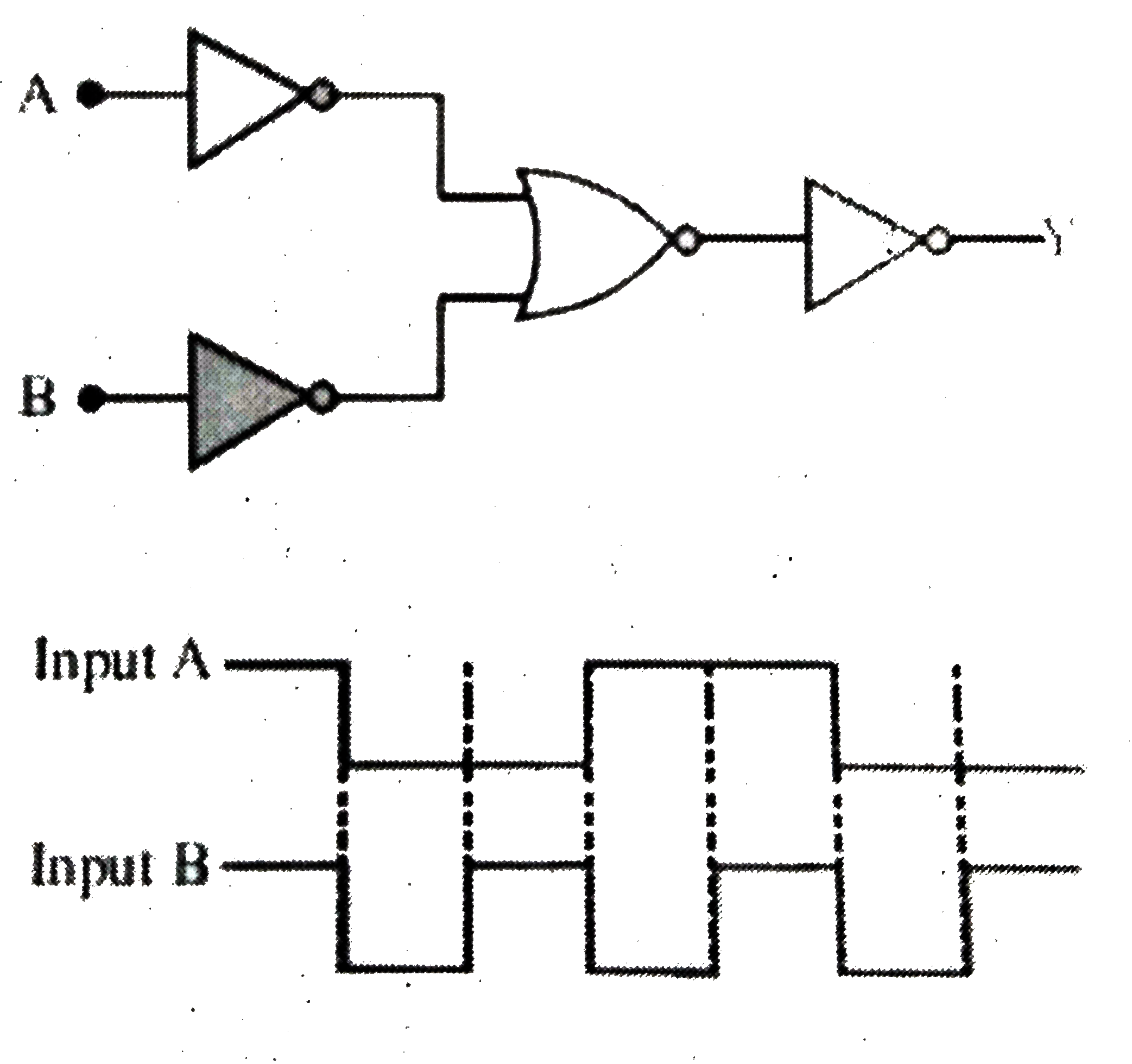
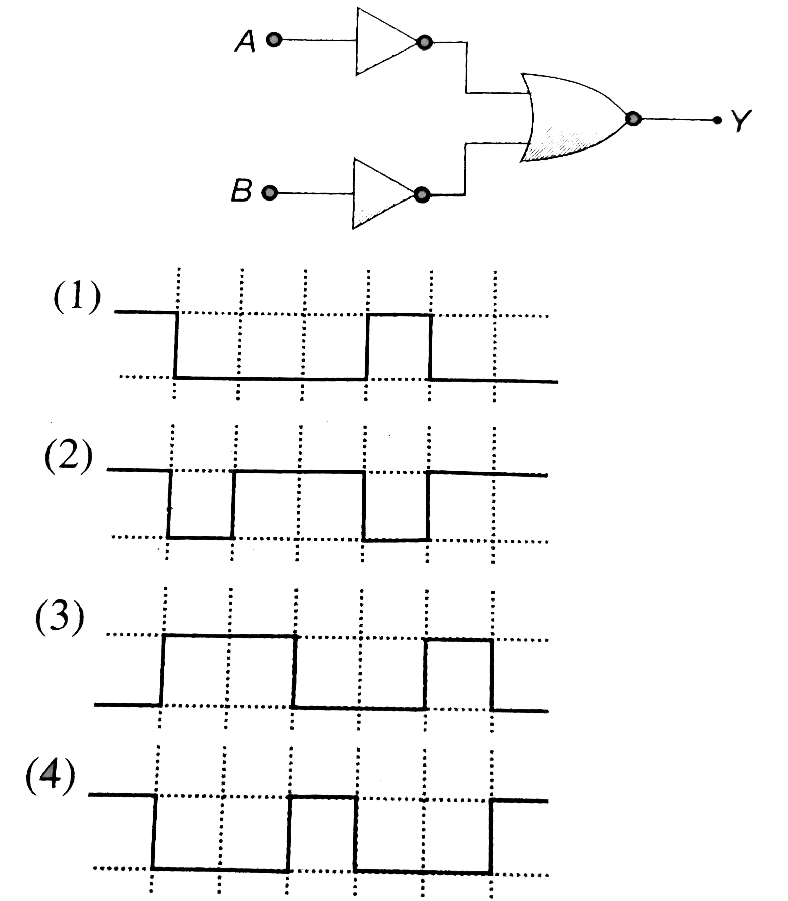
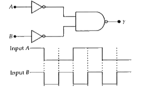
The logic circuit shown has the input waveforms 'A' and 'B' as shown. Pick out the correct output waveform
A

B

C

D

Video Solution
Text Solution
The correct Answer is:A
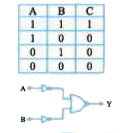
Truth table
|
Topper's Solved these Questions
- SEMICONDUCTOR ELECTRONICSBOOK - NARAYNACHAPTER - SEMICONDUCTOR ELECTRONICSEXERCISE - ADDITIONAL EXERCISE (ASSERTION AND REASON TYPE QUESTIONS :)
19 Videos
- SEMICONDUCTOR ELECTRONICSBOOK - NARAYNACHAPTER - SEMICONDUCTOR ELECTRONICSEXERCISE - EXERCISE -3
43 Videos
- SEMI CONDUCTOR DEVICESBOOK - NARAYNACHAPTER - SEMI CONDUCTOR DEVICESEXERCISE - Level-II (H.W)
36 Videos
- WAVE OPTICSBOOK - NARAYNACHAPTER - WAVE OPTICSEXERCISE - Exercise - 4 Polarisation
9 Videos
Similar Questions
Knowledge Check
The logic circuit shown below has the input waveform 'A' and 'B' as shown. Pick out the correct output waveform
_E01_490_Q01.png)
Output is :-A_E01_490_O01.png) B
B_E01_490_O02.png) C
C_E01_490_O03.png) D
D_E01_490_O04.png)
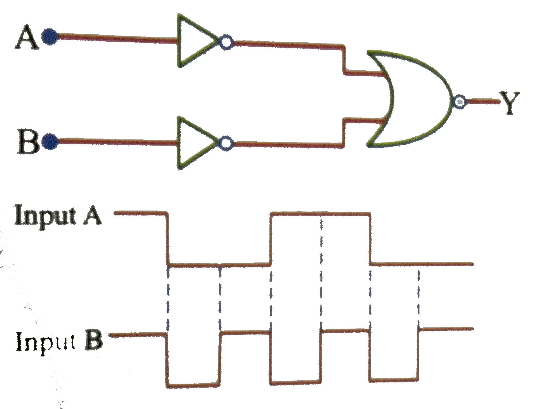
The logic circuit shown below has the input waveforms 'A' and 'B' as shown. Pick out the correct output waveform
 .A
.A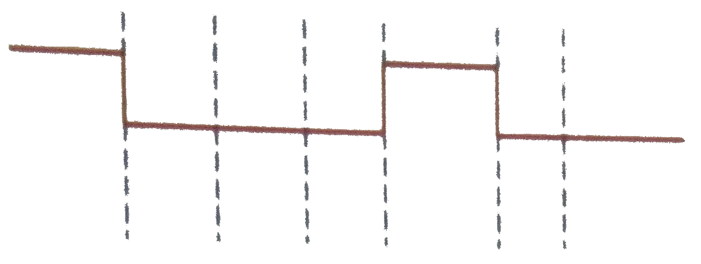 B
B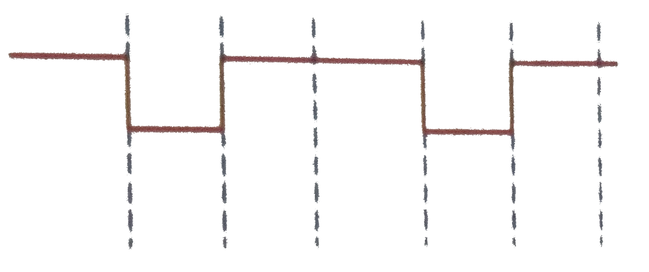 C
C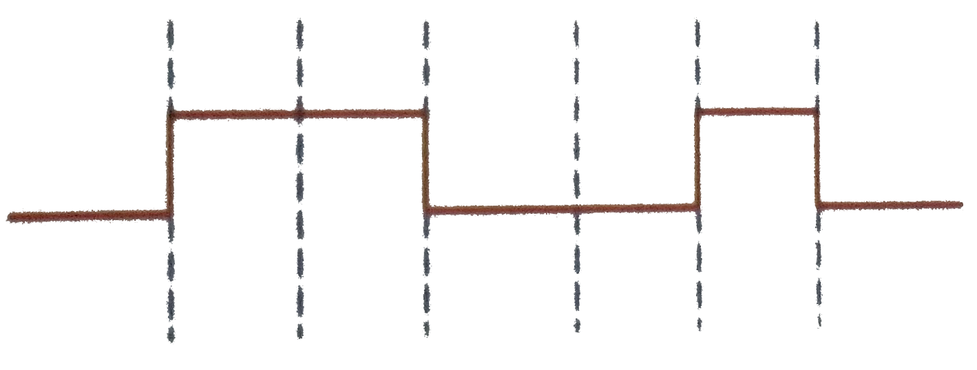 D
D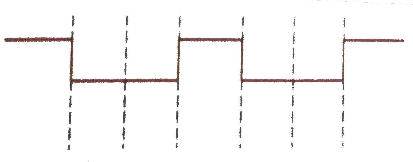
The logic circuit shown belows has the input waveforms 'A' and 'B' as shown. Pick out the correct output waveform
 A
A B
B C
C D
D
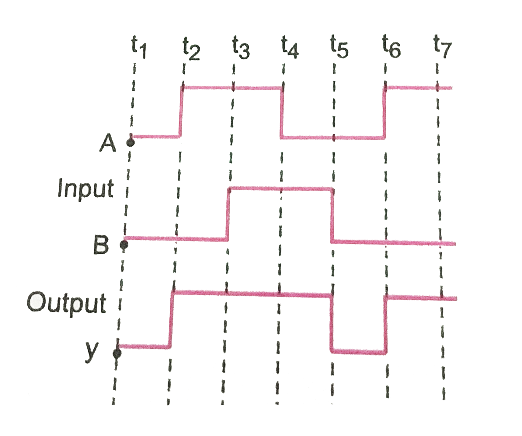
The Fig shown input waveforms A and B to a logic gate. Draw the output waveform for an OR gate. Write the truth table for this logic gate and draw its logic symbol.
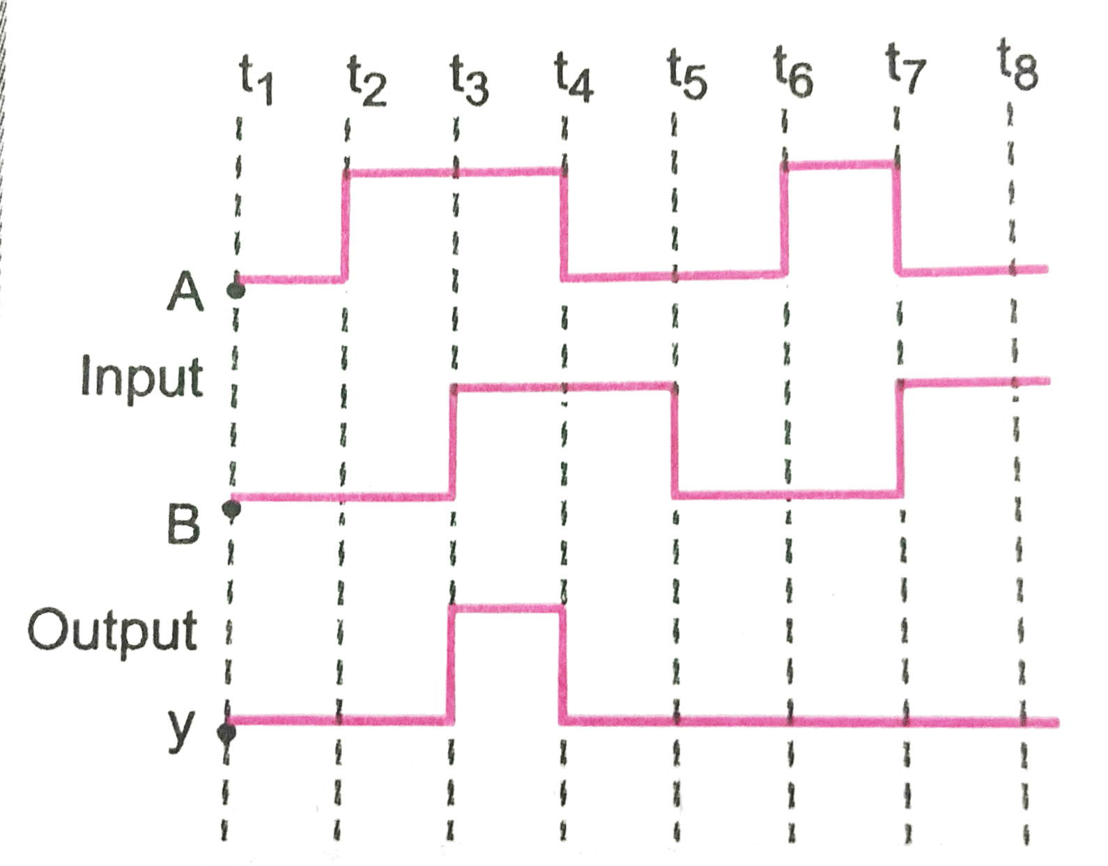
View SolutionThe Fig.shows the input wavwforms A and B for 'AND' gate. Draw the output waveform and write the truth table for this logic gate.
View SolutionThe logic circuit shown below has the inputs waveforms A and B as shown. Pick out the correct output waveform.
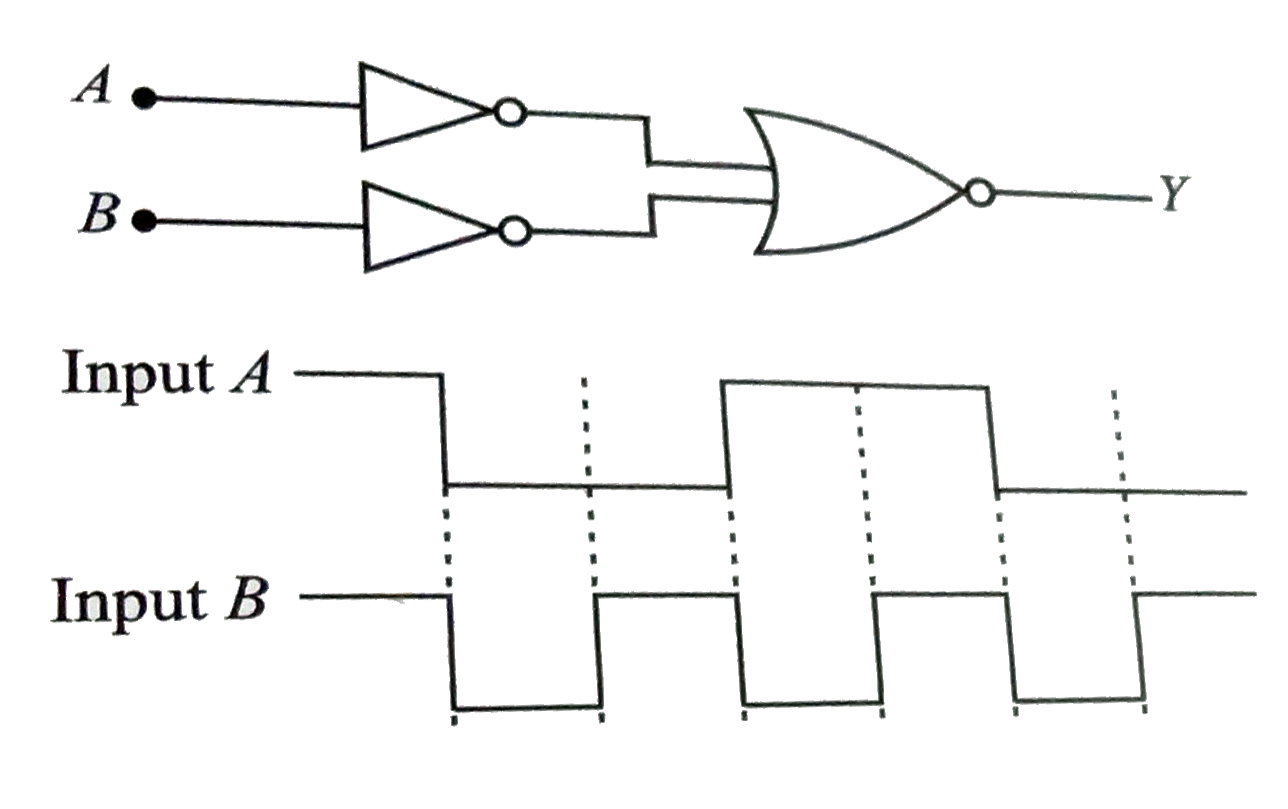
View SolutionThe logic circuit shown below has the input waveforms A and B as shown. Pick out the correct out put waveform.
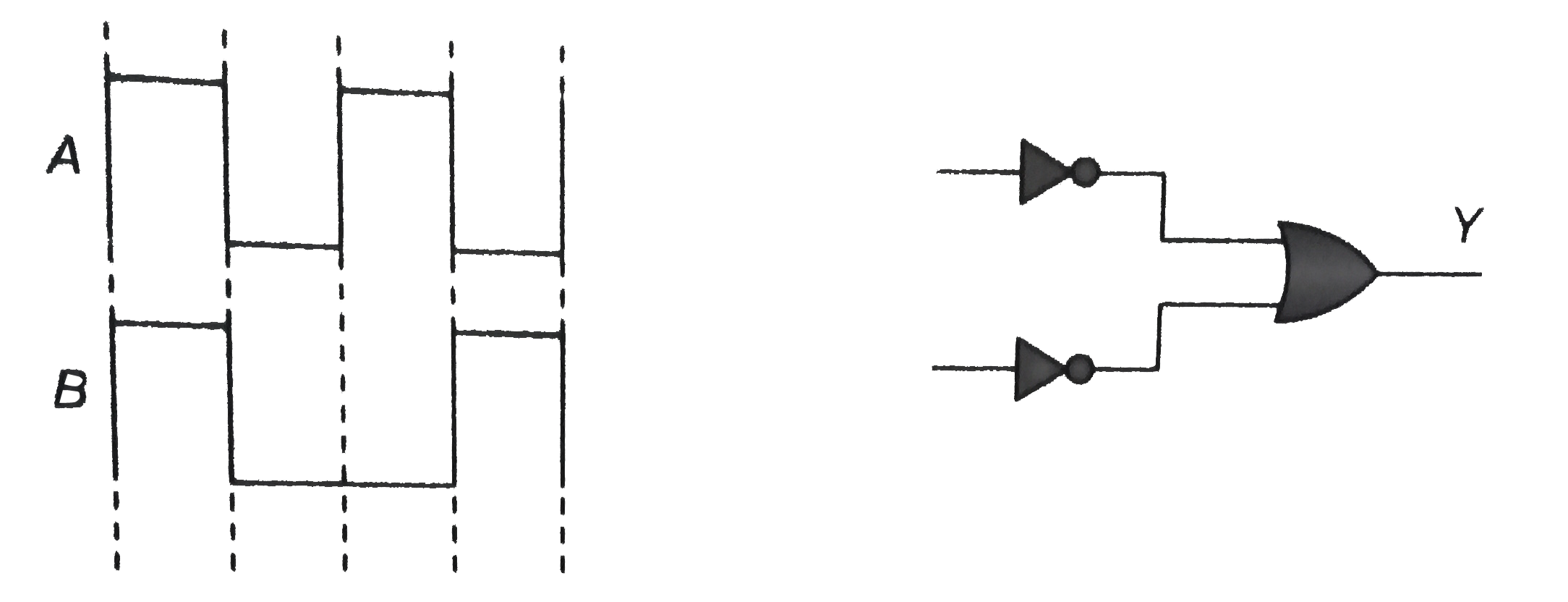
View SolutionIn the given circuit as shown the two input waveform A and B are applied simultaneously. The resultant waveform Y is
View Solution

