Which of the following will NOT be obsered when a multimeter ( operating in resistance measuring mode ) probes connected across a component , are just reversed ?
Multimeter shows an equal deflection in both case i.e., before and after reversing the probes if the chosen component is resistor .
Multimter showns NO deflection in both cases i.e., before and after reversing the probes if the chosen component is metal wire.
Multimeter shows NO deflection in both cases i.e., before and after reversing the probes if the chosen component is capacitor
Multimeter shows a deflection , accompanied by a splash of light out of connected compoenent in one direction and NO deflection on reversing the probes if the chosen component is LED.
To solve the question regarding the behavior of a multimeter in resistance measuring mode when probes are reversed, we will analyze each option step by step.
1. Understanding Multimeter in Resistance Mode:
- When a multimeter is set to measure resistance, it sends a small current through the component being measured and displays the resistance value. The direction of current does not affect the resistance measurement.
2. Analyzing Each Option:
- Option 1: If the component is a resistor, reversing the probes will still yield the same resistance value. This is because resistance is a scalar quantity and does not depend on the direction of the current.
- Conclusion: This option will show a value regardless of probe orientation.
- Option 2: If the component is a capacitor, when measuring resistance, the multimeter will not show any deflection (or reading) because capacitors block direct current (DC) after charging. Therefore, reversing the probes will not change this behavior.
- Conclusion: This option will not show any reading, regardless of probe orientation.
- Option 3: If the component is an inductor, similar to capacitors, inductors also do not provide a resistance reading in DC conditions. Thus, reversing the probes will not yield any reading.
- Conclusion: This option will also not show a reading.
- Option 4: If the component is an LED, it will only allow current to flow in one direction (forward bias). When the probes are reversed, the LED will not glow, indicating that it is not conducting.
- Conclusion: This option will show a difference in behavior based on probe orientation.
3. Final Conclusion:
- The question asks which option will NOT be observed when the probes are reversed. Since capacitors do not show a reading in resistance mode regardless of probe orientation, Option 2 is the correct answer.
Final Answer:
Option 2: A capacitor will not show any reading when the probes are reversed.
- When a multimeter is set to measure resistance, it sends a small current through the component being measured and displays the resistance value. The direction of current does not affect the resistance measurement.
- Option 1: If the component is a resistor, reversing the probes will still yield the same resistance value. This is because resistance is a scalar quantity and does not depend on the direction of the current.
- Conclusion: This option will show a value regardless of probe orientation.
- Conclusion: This option will not show any reading, regardless of probe orientation.
- Conclusion: This option will also not show a reading.
- Conclusion: This option will show a difference in behavior based on probe orientation.
- The question asks which option will NOT be observed when the probes are reversed. Since capacitors do not show a reading in resistance mode regardless of probe orientation, Option 2 is the correct answer.
Option 2: A capacitor will not show any reading when the probes are reversed.
Topper's Solved these Questions
Similar Questions
Knowledge Check
- Question 1 - Select One
Which of the following diodes is operated in reverse bias mode ?
Ap-n junctionBZener diodeCtunnelDSchottky - Question 2 - Select One
Which of the following is not a component of operating surplus ?
AInterestBRentCRoyalityDCompensation of Employees - Question 3 - Select One
To measure the resistance of a device using Ohm's law the mode of connection used is
Aammeter in series, voltmeter in parallelBvoltmeter in series, ammeter in parallelCboth ammeter and voltmeter in seriesDboth ammeter and voltmeter in parallel
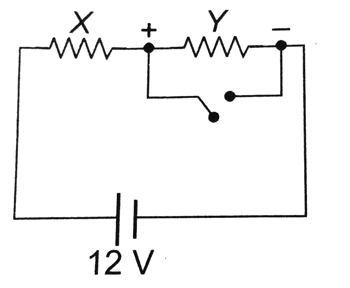
When an ammter of negligible internal resistance is inserted in series with circuit it reads 1A When the voltmeter of very large resistance is connected across X it reads 1V. When the point A and B are shorted by a conducting wire, the voltmeter meausres 10V across the battery. The internal resistance of the battery is equal to
 View Solution
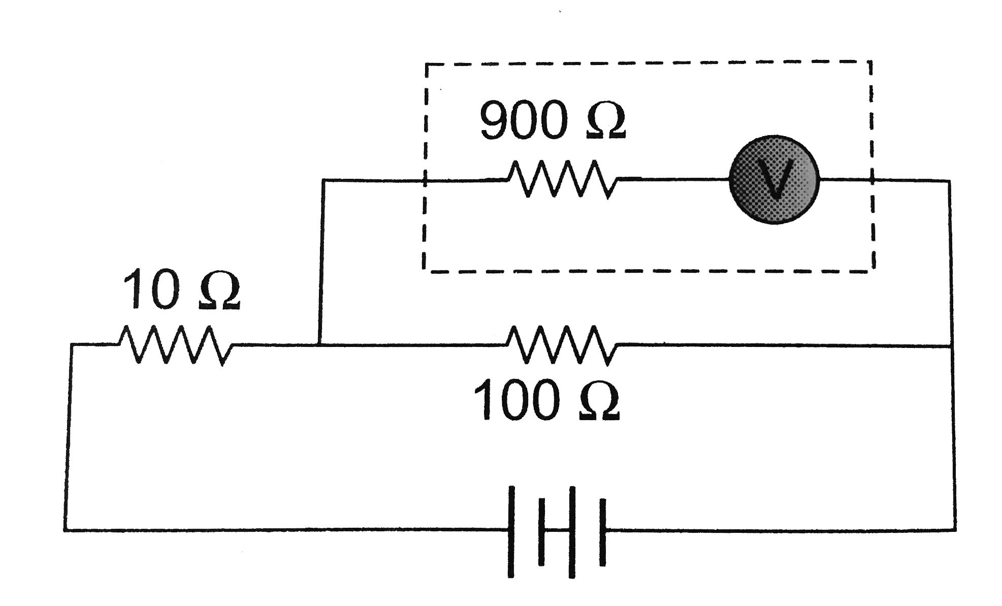
The potential difference across the 100Ω resistance in the following circuit is measured by a voltmeter of 900Ω resistance. The percentage error made in reading the potential difference is
 View Solution
Consider the diagram shown below.
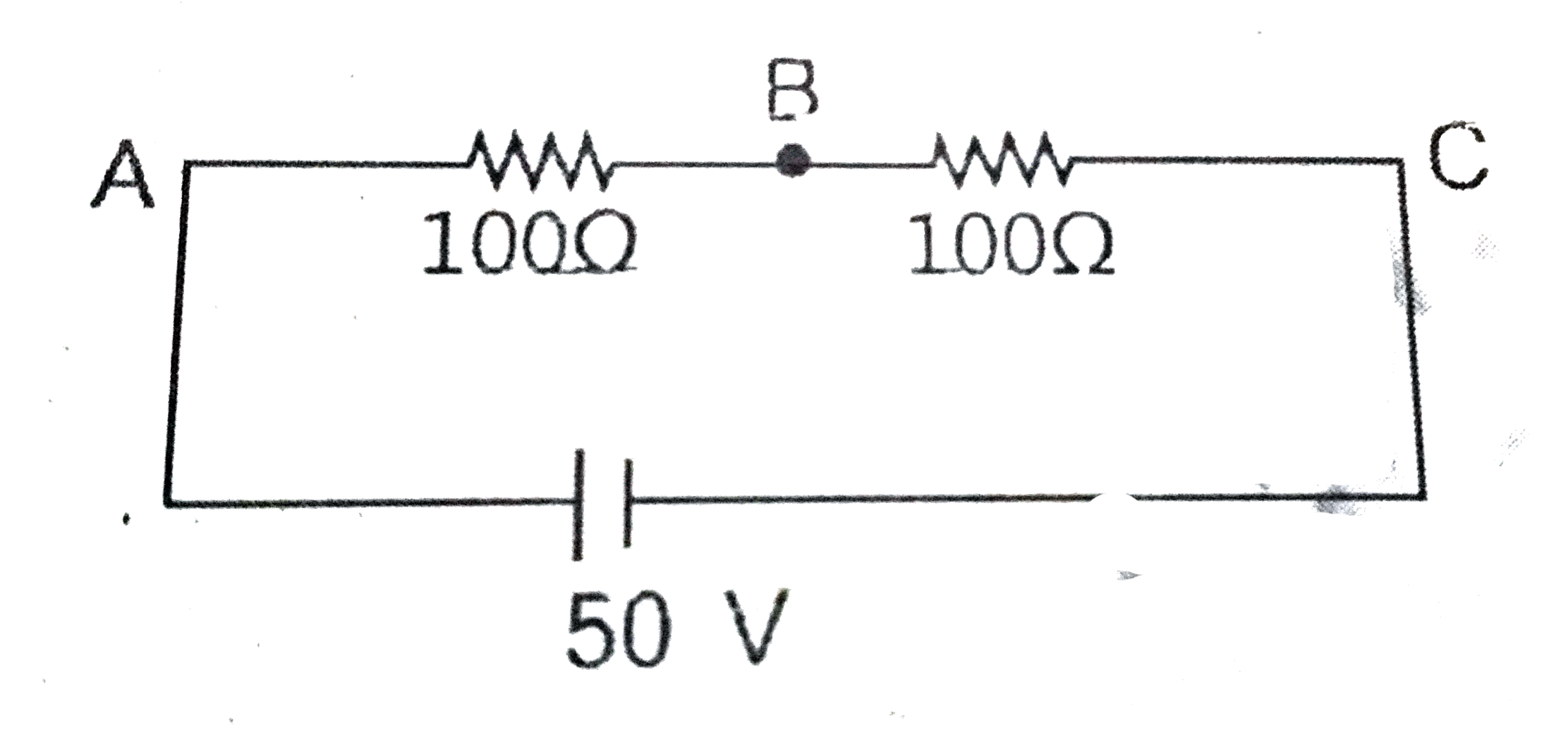
A voltmeter of resistance 150Ω is connected across A and B. The potential drop across B and C measured by voltmeter isView SolutionConsider the diagram shown below.
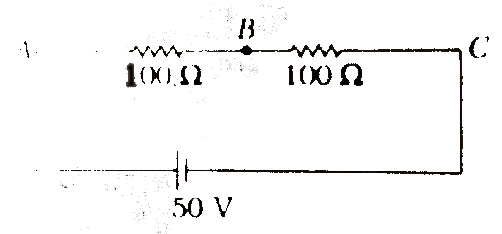
A Voltmeter of resistance 150Ω is connected across A and B. The potential drop across B and C measured by voltmeter isView SolutionIn Fig.6.59, when an ideal voltmetre is connected across 4000Ω resistance, it reads 30V. If the voltmeter is connected across 3000Ω resistance, it will read
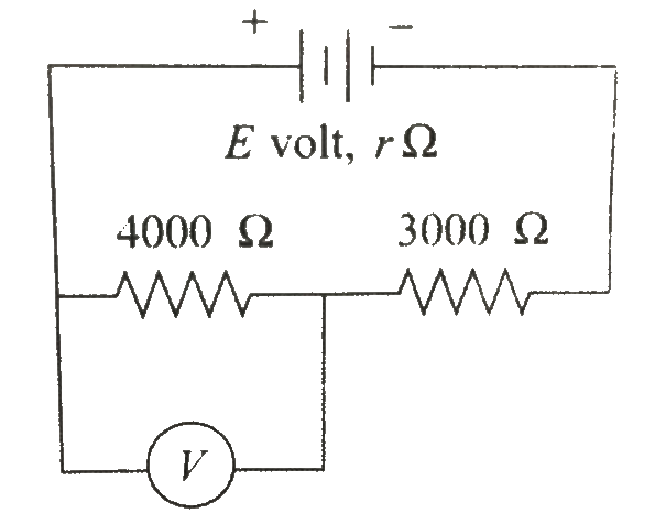 View Solution

