The following diagram shows the circuit for the comparision of e.m.f. of the cells. The circuit can be corrected by:-
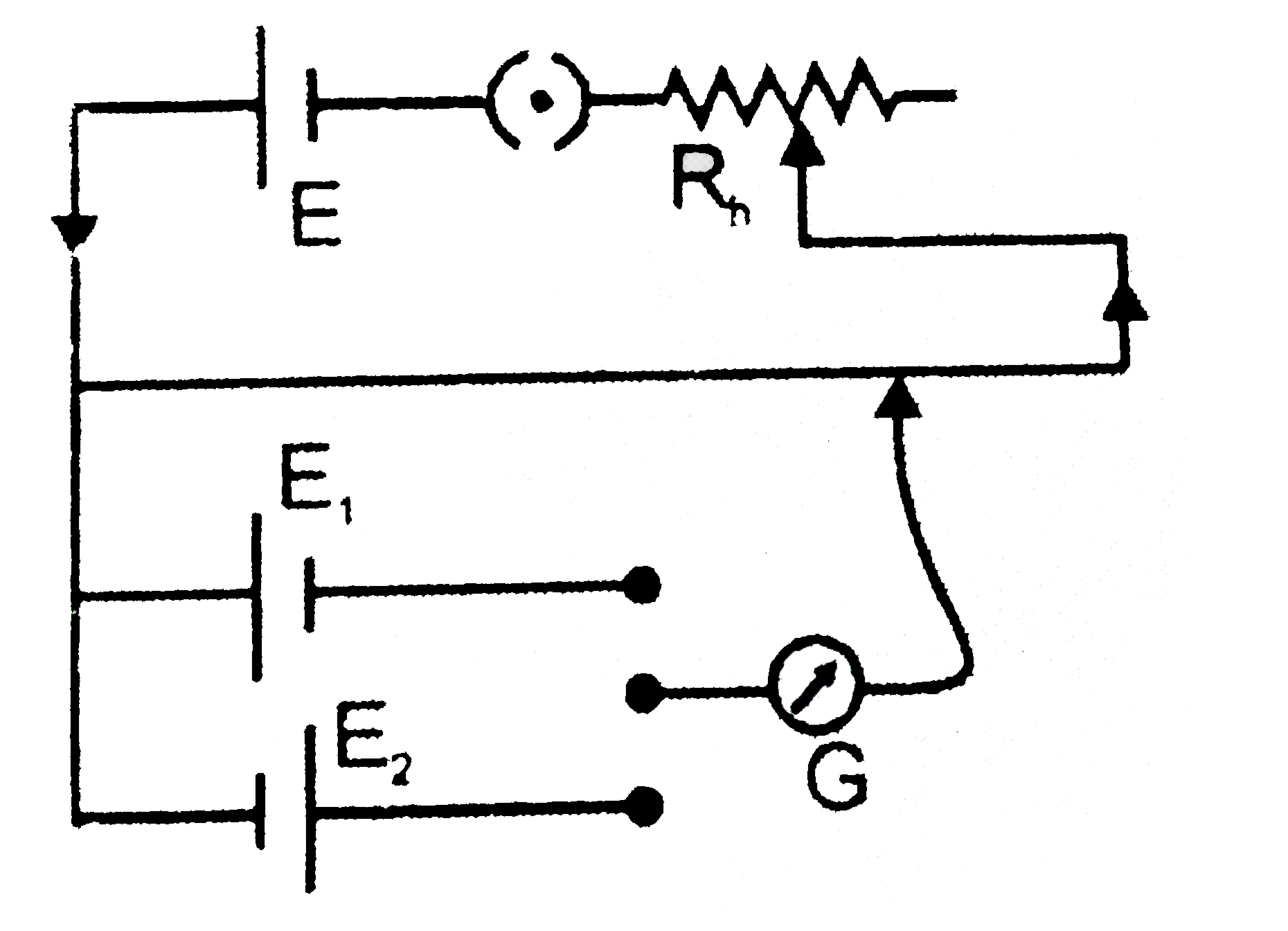
Reversing the terminals of E
Reversing the terminals of E1
Reversing the terminals E2
Reversing the current in Rh.
The correct Answer is:3
Step by step video, text & image solution for The following diagram shows the circuit for the comparision of e.m.f. of the cells. The circuit can be corrected by:- by Physics experts to help you in doubts & scoring excellent marks in Class 12 exams.
Updated on:21/07/2023Topper's Solved these Questions
Similar Questions
Knowledge Check
The e.m.f. of two cells can be compared by
ApotentiometerBammeterCluxmeterDspeedometerWhich one of the following equation is correct for the circuit shown. The currents in each branch of circuit are indicated and all three cells are ideal
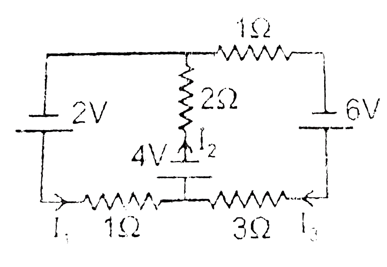 A2−I1−2I2=0B2−2I0−2I2−4I3=0C4−I1+4I3=0D−2−I1−2I2=0
Which one of the following equation is correct for the circuit shown. The currents in each brach of circuit are indicated and all three cells are ideal.
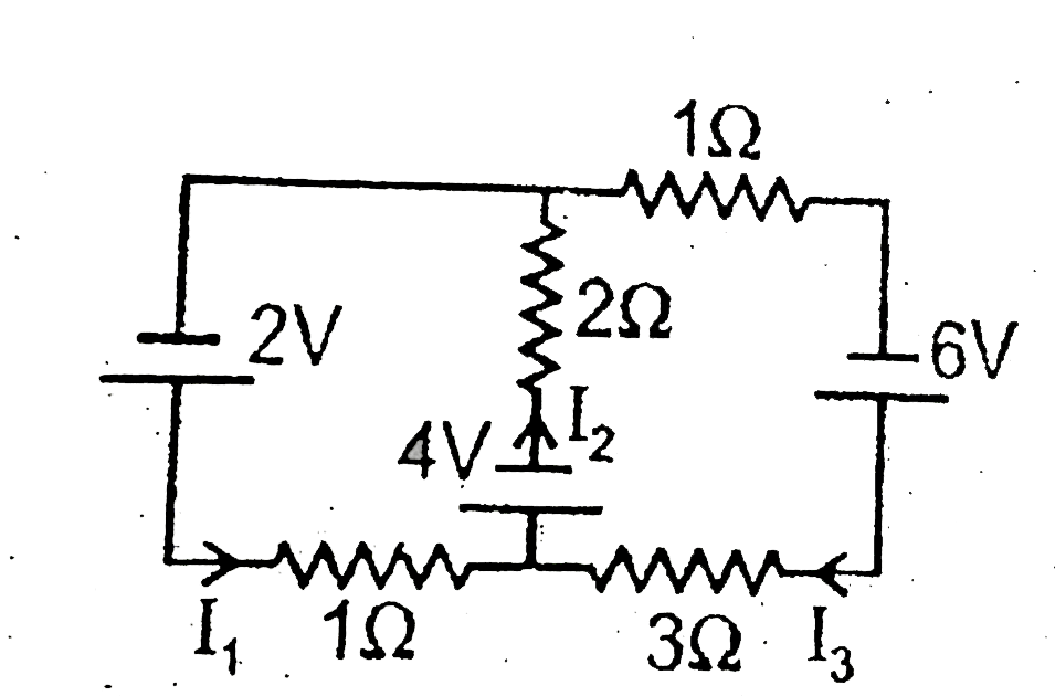 A2−I1−2I2=0B2−2I1−2I2−4I3=0C4−I1+4I3=0D−2−I1−2I2=0
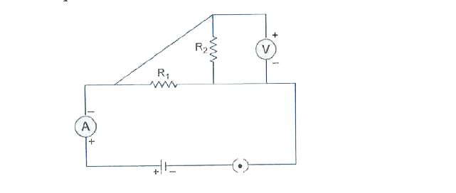
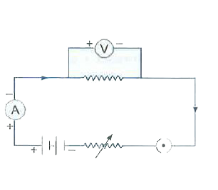
The following circuit diagram shows the experimental set-up for the study of dependence of current on potential difference. Which two circuit components are connected in series?
View SolutionThe circuit shown in the diagram is in resonance. Power factor of the circuit is
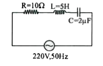
View SolutionThe circuit shown in the diagram is in resonance. Power factor of the circuit is

View SolutionDraw a circuit diagram showing the biasing of a photodiode.
View SolutionIn the following circuit the resultant e.m.f. between AB is:
View Solution

