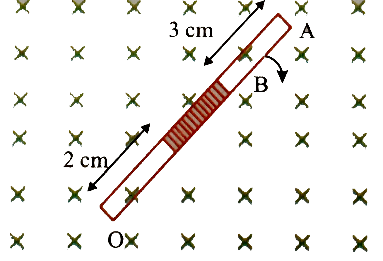
A rod of length 10cm made up of conducting and non-conducting material (shaded part is non-conducting). The rod is rotated with constant angular velocity 10rad/s about point O, in constant magnetic field of 2T as shown in the figure. The induced emf between the point A and B of rod will be:
0.029v
0.1v
0.051v
0.064v
The correct Answer is:C
Step by step video, text & image solution for A rod of length 10 cm made up of conducting and non-conducting material (shaded part is non-conducting). The rod is rotated with constant angular velocity 10 rad//s about point O, in constant magnetic field of 2 T as shown in the figure. The induced emf between the point A and B of rod will be: by Physics experts to help you in doubts & scoring excellent marks in Class 12 exams.
Topper's Solved these Questions
- BOOK - RESONANCECHAPTER - ELECTROMAGNETIC INDUCTIONEXERCISE - Exercis-2 PART 115videos
ELECTROMAGNETIC INDUCTION
- BOOK - RESONANCECHAPTER - ELECTROMAGNETIC INDUCTIONEXERCISE - Exercis-2 PART 217videos
ELECTROMAGNETIC INDUCTION
- BOOK - RESONANCECHAPTER - ELECTROMAGNETIC INDUCTIONEXERCISE - Exercis-163videos
ELECTROMAGNETIC INDUCTION
- BOOK - RESONANCECHAPTER - ELECTRODYNAMICSEXERCISE - Advanced level problems31videos
ELECTRODYNAMICS
- BOOK - RESONANCECHAPTER - ELECTROSTATICSEXERCISE - HLP39videos
ELECTROSTATICS
Similar Questions
A conducting rod of length l is rotating with constant angular velocity ω about point O in a uniform magnetic field B as shown in the figure . What is the emf induced between ends P and Q ?
 View Solution
A copper rod of length l rotates an angular velocity ω in a uniform magnetic field B as show in figure . What is the induced emf across its ends ?
 View Solution
Knowledge Check
- Question 1 - Select One
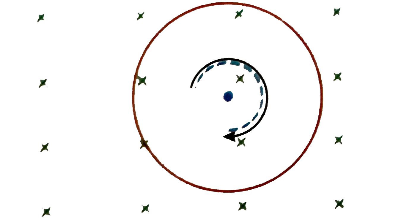
A non-conducting disk of radius R is rotating about its own axis with constant angular velocity ω in a perpendicular uniform magnetic field B as shown in figure. The emf induced between centre and rim of disk is
 ABωR22BBωR2CZeroDBωR23
 - Question 2 - Select One
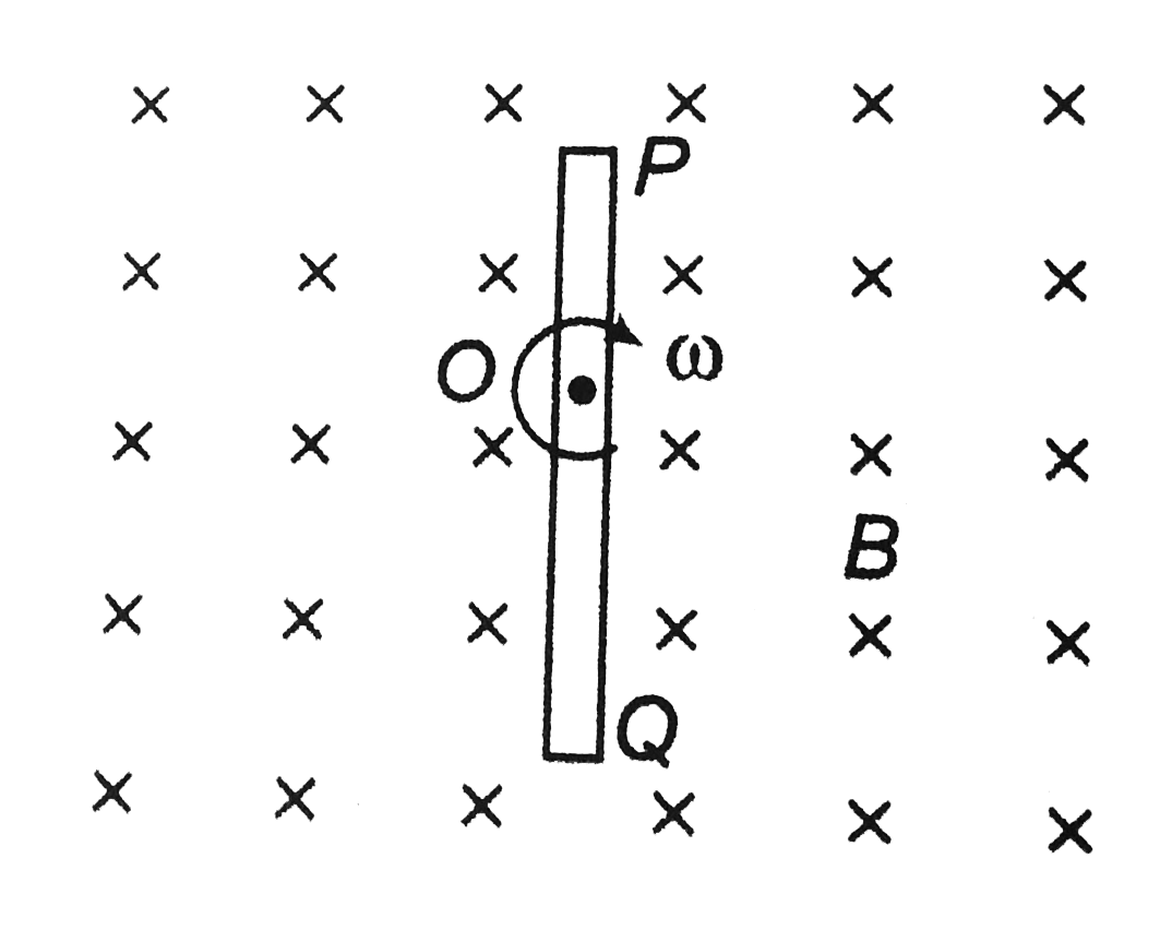
A rod is rotating with a constant angular velocity ω about point O (its centre) in a magnetic field B as shown. Which of the folloiwng figure correctly shows the distribution of charge inside the rod?
 A
A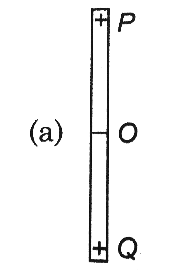 B
B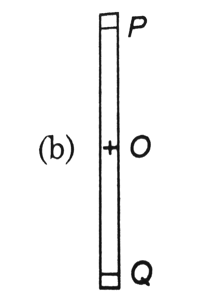 C
C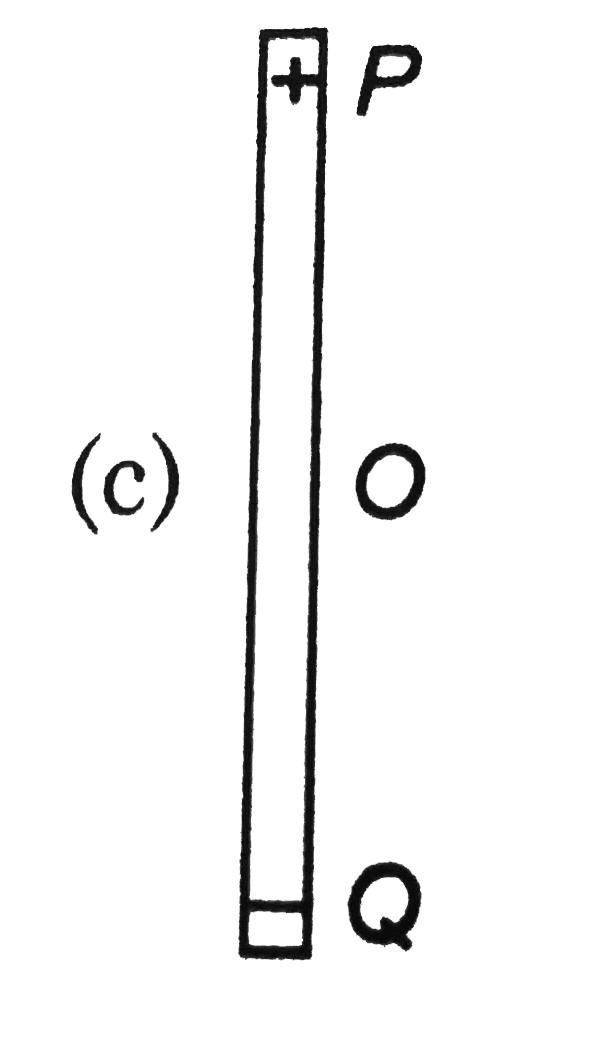 D
D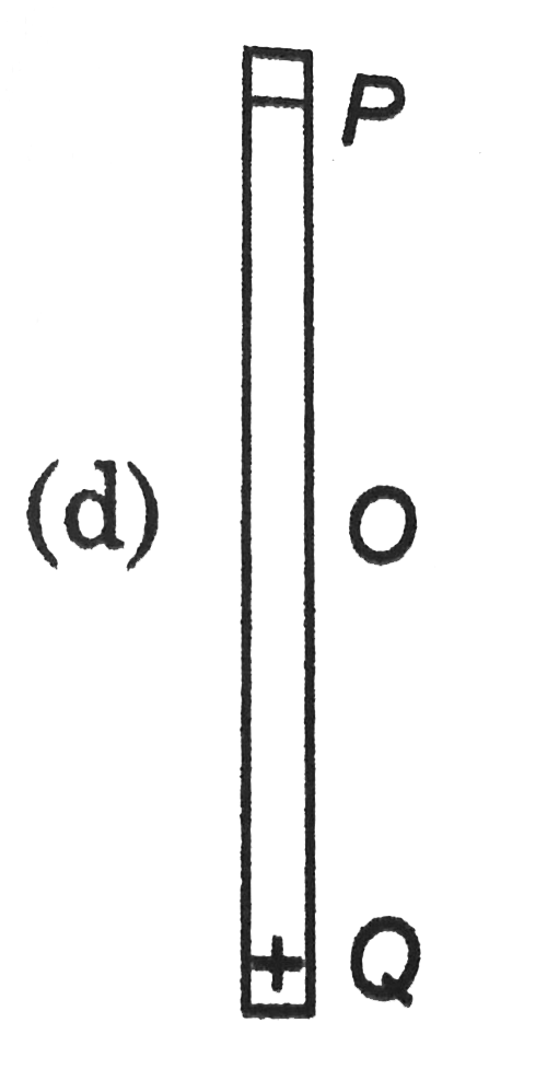
- Question 3 - Select One
A metal rod of length 2m is rotating with an angular velocity of 100rad/sec in a plane perpendicular to a uniform magnetic field of 0.3T. The potential difference between the ends of the rod is
A30VB40VC60VD600V
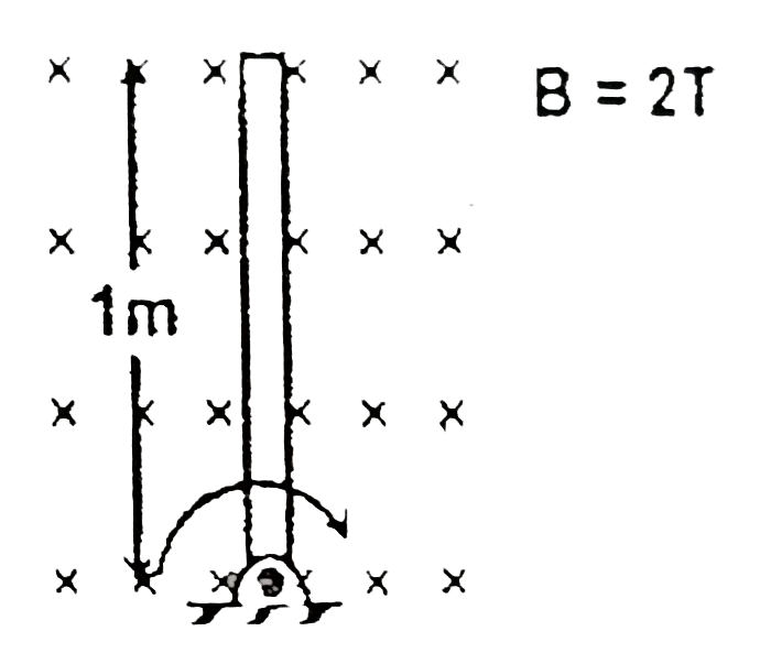
A rod of length 1m rotates about one of its end points with an angular velocity 2rad/sec in a plane perpendicular to the magnetic field B=2T as shown in the figure. Then find magnitude of electric field (in SI unit) at the mid point of the rod.
 View Solution
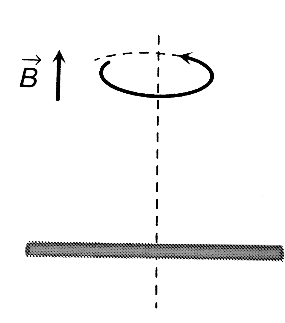
A metallic rod of length lis hinged at one end and the other end is rotated with a constant angular speed ω about an axis passing through the hinge. A constant and uniform magnetic field B, parallel to the axis of rotation exists everywhere. The induced emf between the two ends of rod is 12Blω2.
View SolutionA conducting rod of 1m length rotating with a frequency of 50 rev/sec. about its one of end inside the uniform magnetic field of 6.28 mT. The valu of induced emf between end of rod is :-
View SolutionA conducting rod of length 2l is rotating with constant angular speed w about its perpendicular bisector. A uniform magnetic field B exists parallel to the axis of rotation. The e.m.f. induced between two ends of the rod is
 View Solution
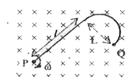
When a 'j' shaped conducting rod is rotating in its own plane with constant angular velocity ω about one of its ends P in a uniform magnetic field →B ( directed normally into the plane of paper ) the magnitude of emf induced across it will be
 View Solution

