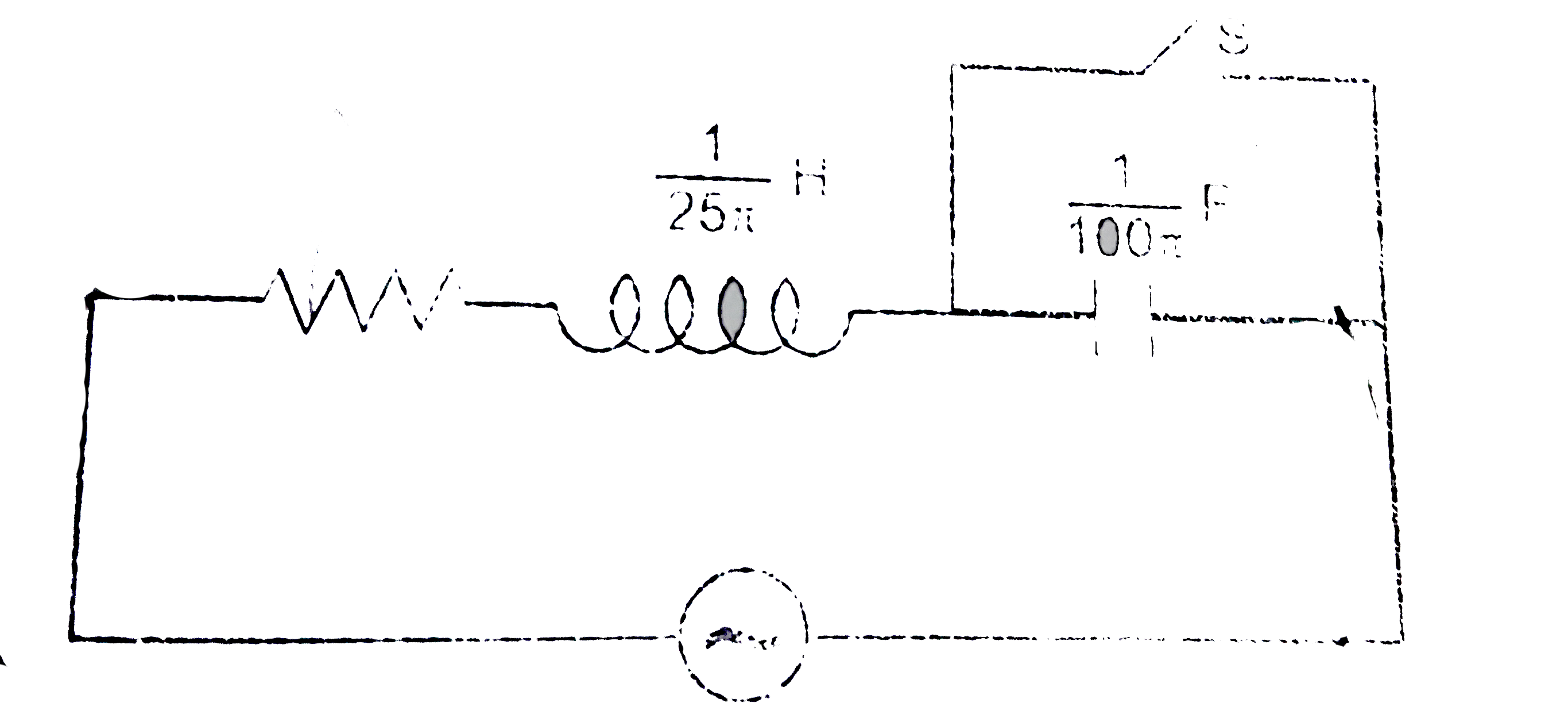
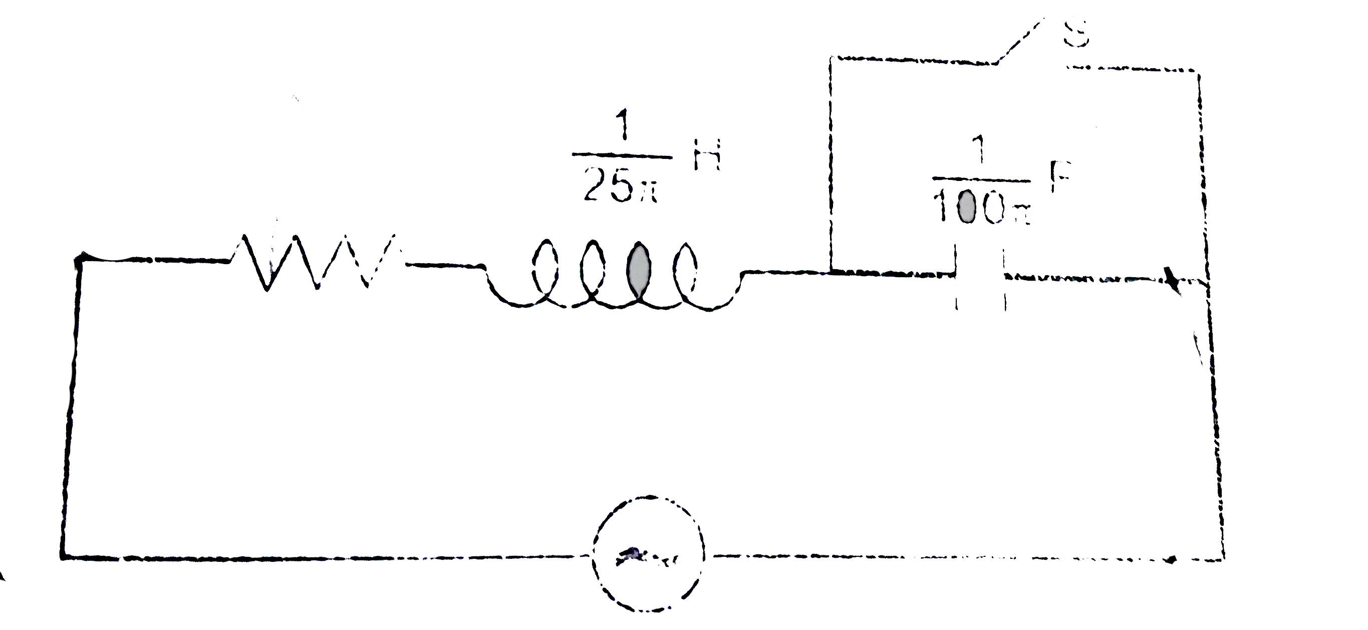
In the LCR circuit shown in figure unknown resistance and alternating voltage source are connected.When swith S is closed then there is a phase difference of π4 between current and applied voltage and voltage across resister is 100√2V.When switch is open current and applied voltage are in same phase.Neglecting resistance of connecting wire answer the following questions :
Average power consumption in the circuit when S is open:
2500W
3000W
5000W
1250W
The correct Answer is:C
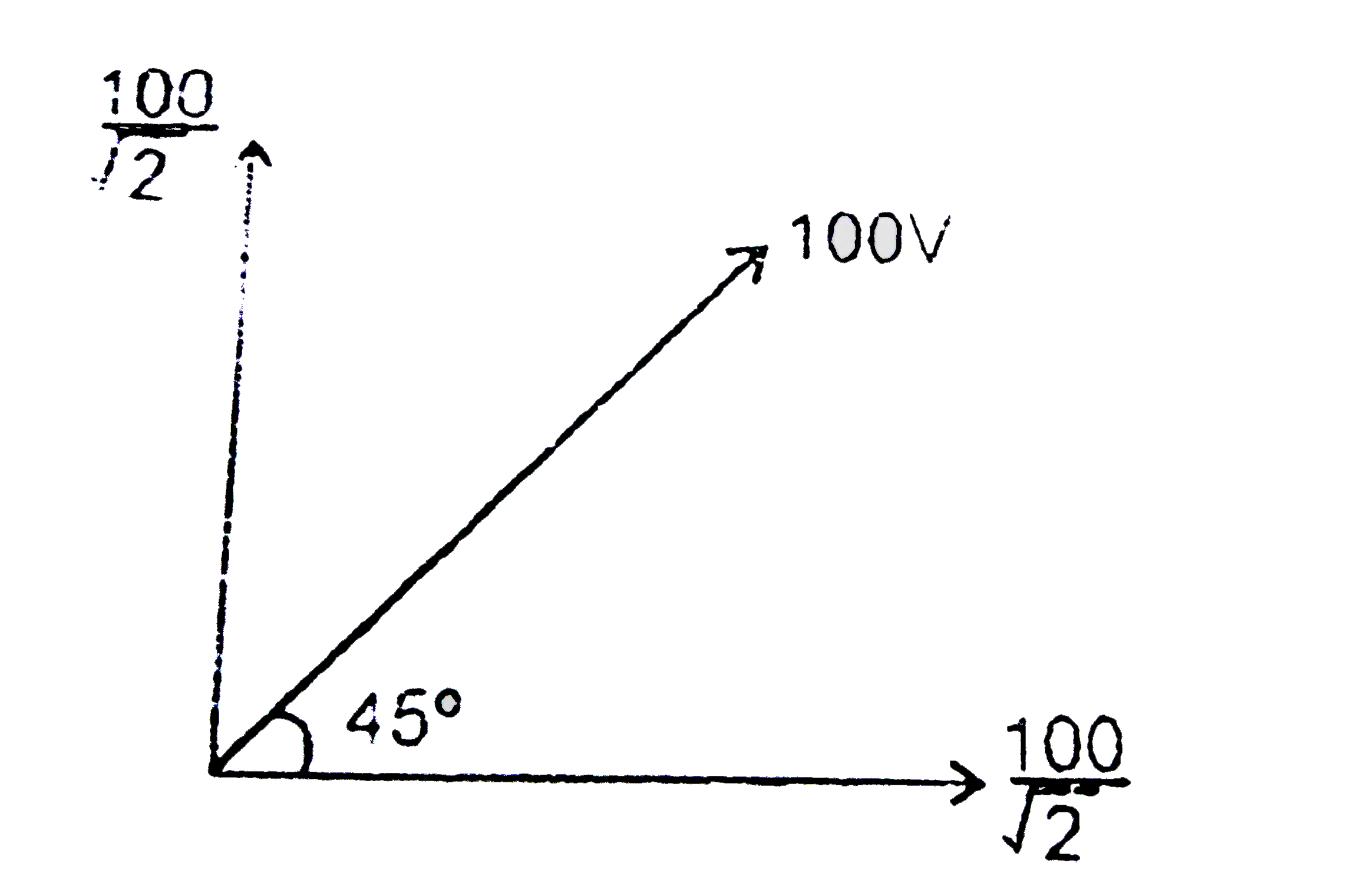
When switch is closed
Vrms(applied)=100 volts
Vpeak(applied)=100√2
When switch is open f=12π√125π×1100π=502=25Hz
Resistance R=XL=XC=2πfL=2Ω
Average power consumption =(1002)22=100002=5000W
Topper's Solved these Questions
- ALTERNATING CURRENTBOOK - RESONANCECHAPTER - ALTERNATING CURRENTEXERCISE - Exercise -3 Part-1
7 Videos
- ALTERNATING CURRENTBOOK - RESONANCECHAPTER - ALTERNATING CURRENTEXERCISE - Exercise -3 Part-2
3 Videos
- ALTERNATING CURRENTBOOK - RESONANCECHAPTER - ALTERNATING CURRENTEXERCISE - Exercise -2 Part-3
14 Videos
- ATOMIC PHYSICSBOOK - RESONANCECHAPTER - ATOMIC PHYSICSEXERCISE - Advanved level problems
17 Videos
Similar Questions
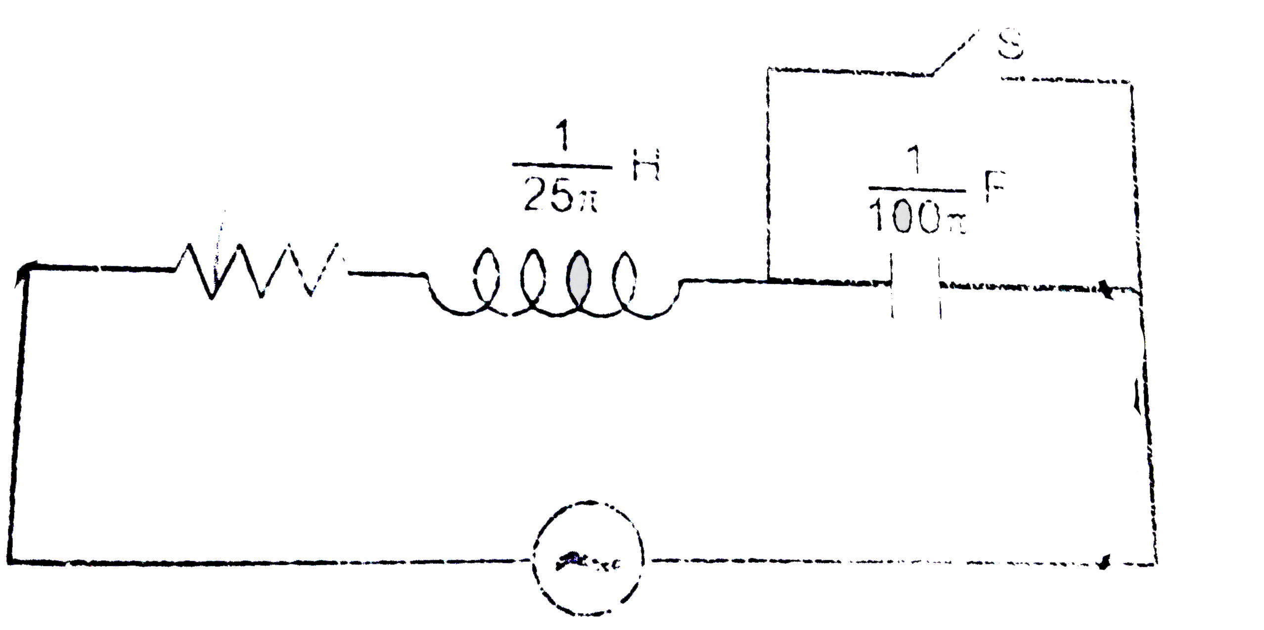
In the LCR circuit shown in figure unknown resistance and alternating voltage source are connected.When swith S is closed then there is a phase difference of π4 between current and applied voltage and voltage across resister is 100√2V.When switch is open current and applied voltage are in same phase.Neglecting resistance of connecting wire answer the following questions :
Resonance frequency of circuit is:
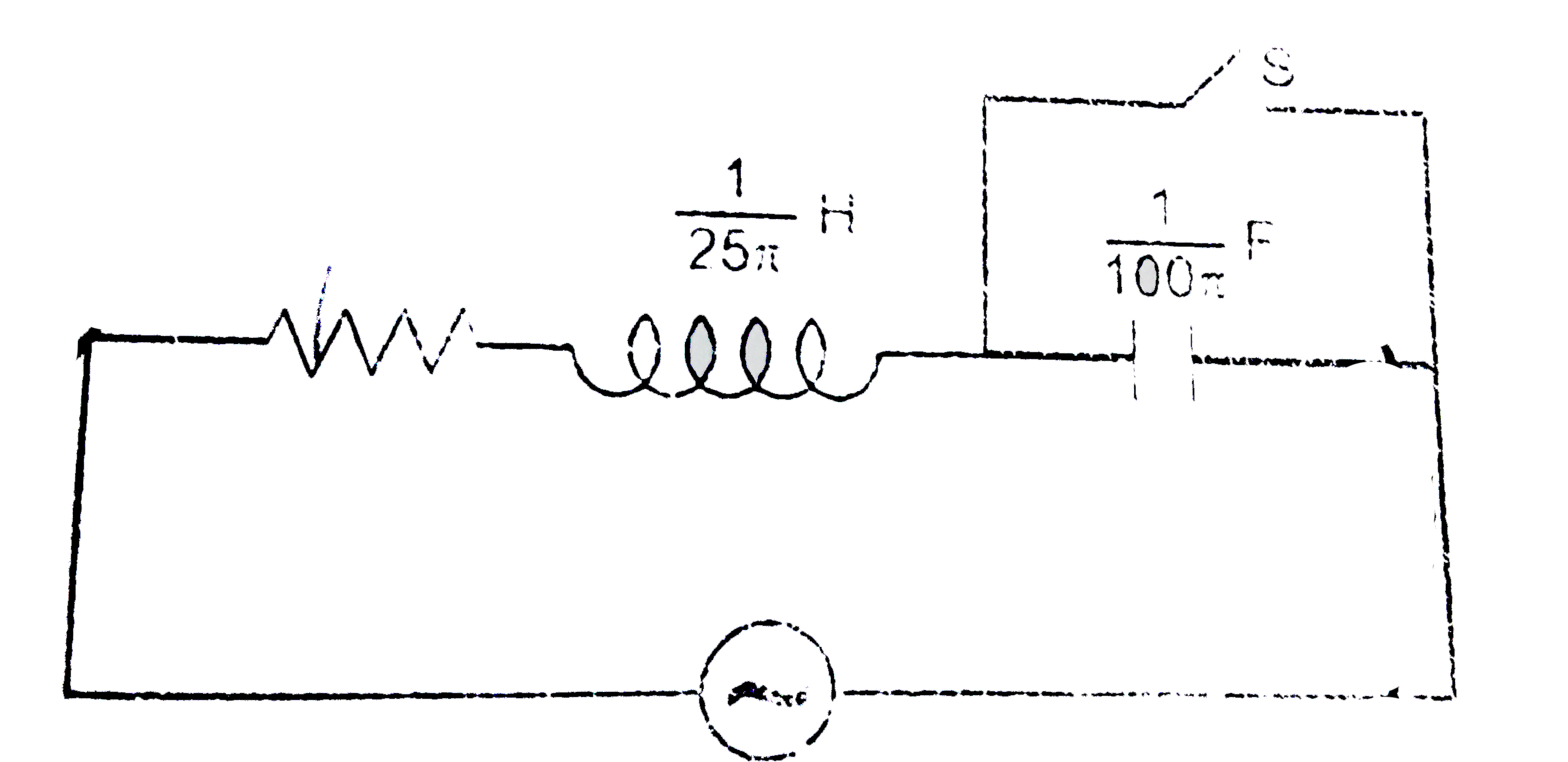
View SolutionIn the LCR circuit shown in figure unknown resistance and alternating voltage source are connected.When swith S is closed then there is a phase difference of π4 between current and applied voltage and voltage across resister is 100√2V.When switch is open current and applied voltage are in same phase.Neglecting resistance of connecting wire answer the following questions :
Peak voltage of applied voltage sources is:
View Solution
Knowledge Check
In the LCR circuit shown in figure unknown resistance and alternating voltage source are connected.When swith S is closed then there is a phase difference of π4 between current and applied voltage and voltage across resister is 100√2V.When switch is open current and applied voltage are in same phase.Neglecting resistance of connecting wire answer the following questions :
Resonance frequency of circuit is:
 A50HzB25HzC75HzDData insufficient for calculation
In the LCR circuit shown in figure unknown resistance and alternating voltage source are connected.When swith S is closed then there is a phase difference of π4 between current and applied voltage and voltage across resister is 100√2V.When switch is open current and applied voltage are in same phase.Neglecting resistance of connecting wire answer the following questions :
Peak voltage of applied voltage sources is:
 A200√2VB100VC100√2VD100√2V
In the LCR circuit shown in figure unknown resistance and alternating voltage source are connect Then switch 'S' is closed then there is a phase difference of π4 between current and applied voltage and voltage accross resister 100√2V is phase. Neglecting resistance of connecting wire answer the following questions:
Average power consumption in the circuit when 'S' is openA2500WB3000WC5000WD1250W
In an L-R circuit, an inductance of 0.1 H and a resistance of 1Ω are connected in series with an ac source of voltage V = 5 sin 10 t. The phase difference between the current and applied voltage will be
View SolutionIn an L-R circuit, an inductance of 0.1 H and a resistance of 1Ω are connected in series with an ac source of voltage V = 5 sin 10 t. The phase difference between the current and applied voltage will be
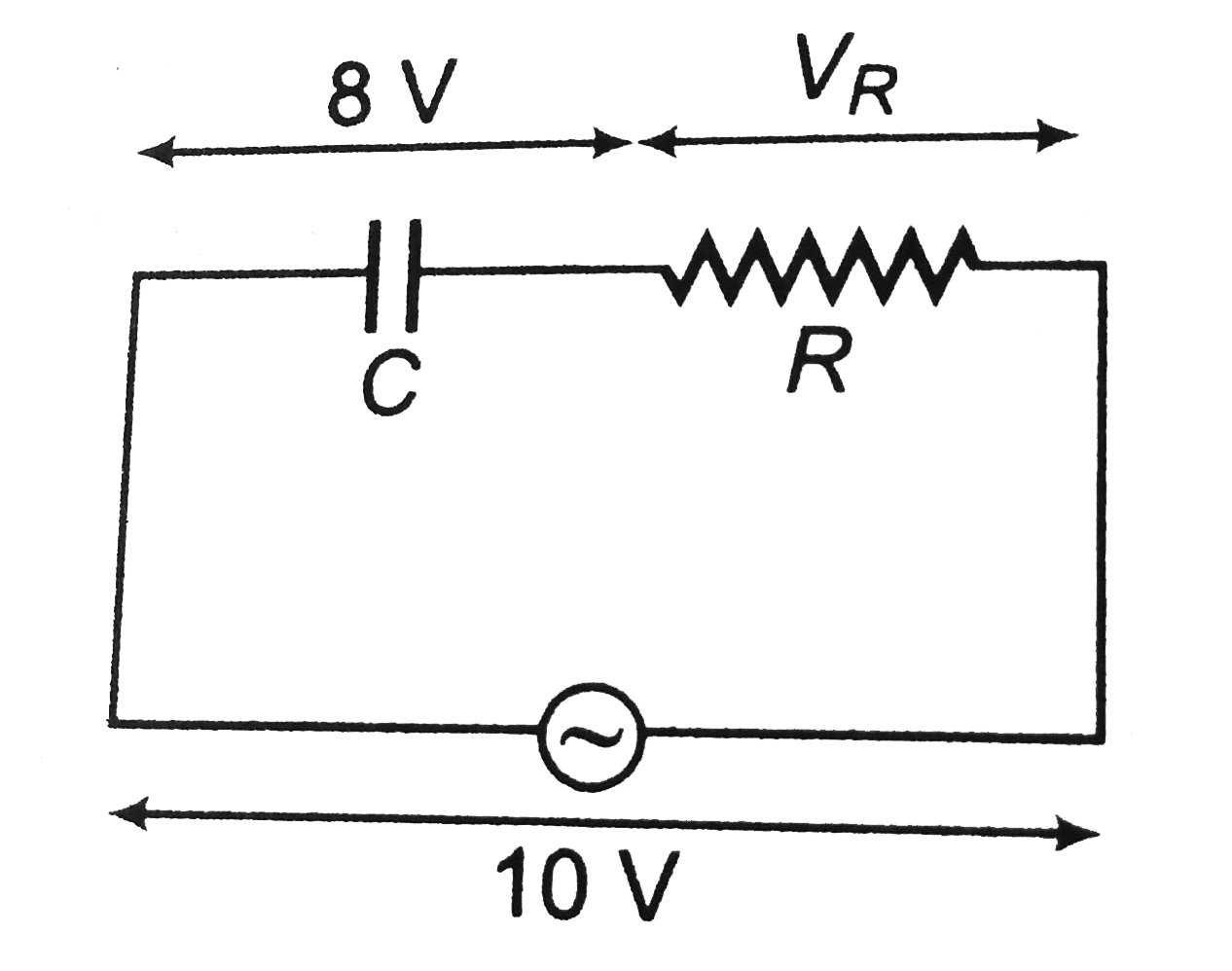
View SolutionIn a series C−R circuit shown in figureure, the applied voltage is 10V and the voltage across capacitor is found to8V. The voltage across R, and the phase difference between current and the applied voltage will respectively be
 .
.
View SolutionIn a series C−R circuit shown in figureure, the applied voltage is 10V and the voltage across capacitor is found to8V. The voltage across R, and the phase difference between current and the applied voltage will respectively be
 .
.
View SolutionIn a LCR series circuit, if the phase difference between applied voltage and current is zero then
View Solution
