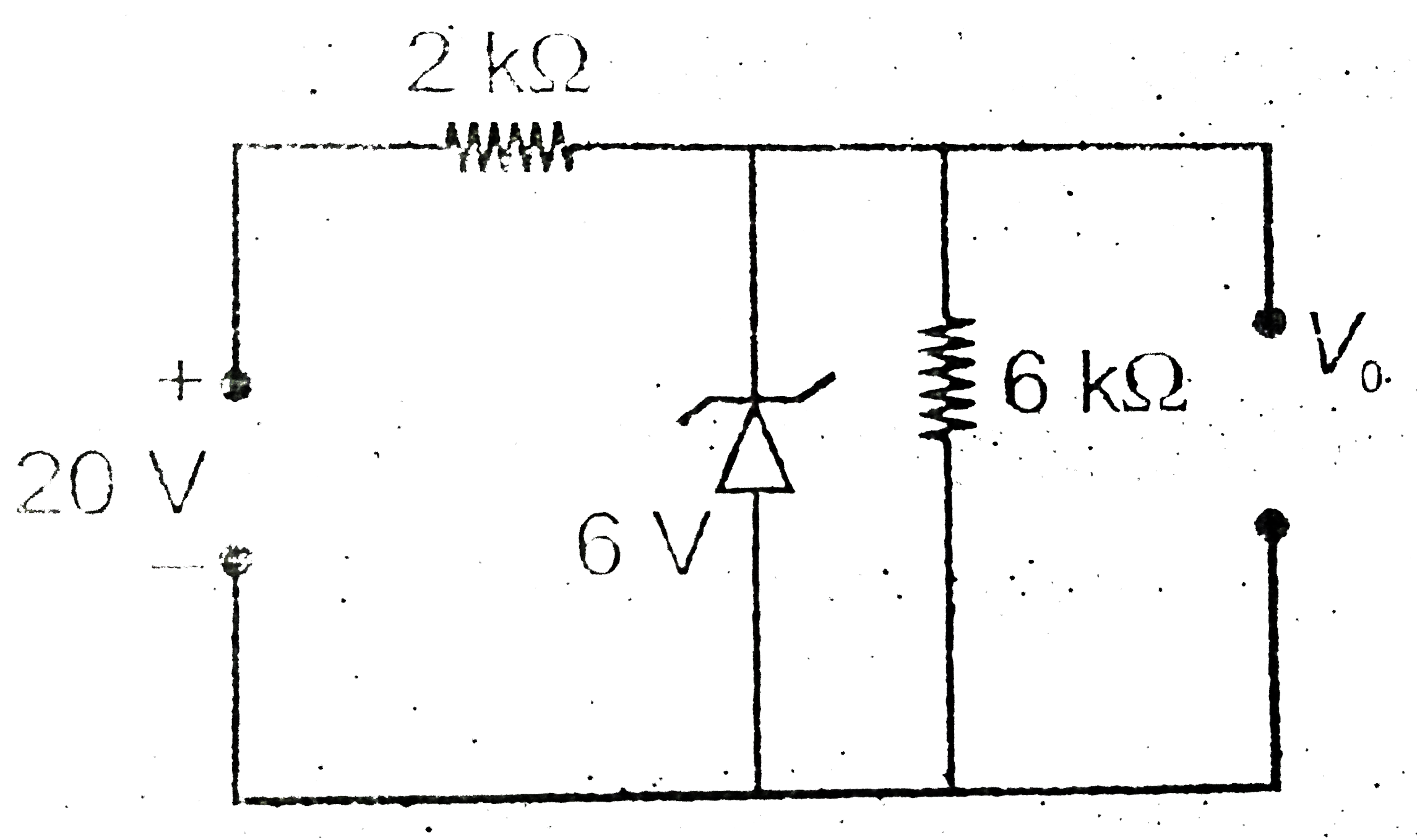
For the given input voltage wavelength Vin(t) , the output voltage waveform (V0)(t) , across the capacitor is correctly depicted by :
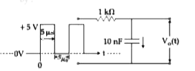


Step by step video & image solution for For the given input voltage wavelength V_("in")(t) , the output voltage waveform (V_0)(t) , across the capacitor is correctly depicted by : by Physics experts to help you in doubts & scoring excellent marks in Class 12 exams.
Updated on:21/07/2023Topper's Solved these Questions
Similar Questions
Knowledge Check
Let q be the charge on the capacitor at any time t. The voltage V across the capacitor is
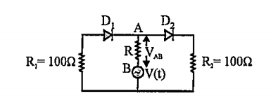
AVmsinωt=qCBVmcosωt=2VCCVmcosωt=q2CDVmsinωt=2qCIn the circuit given below, V(t) is the sinusoidal voltage source, voltage drop VAB(t) across the resistance R is
 Ais half wave rectifiedBis full wave rectifiedChas the same peak value in the positive and negative half cyclesDhas different peak values during positive and negative half cycle
In the circuit given below, V(t) is the sinusoidal voltage source, voltage drop VAB(t) across the resistance R is
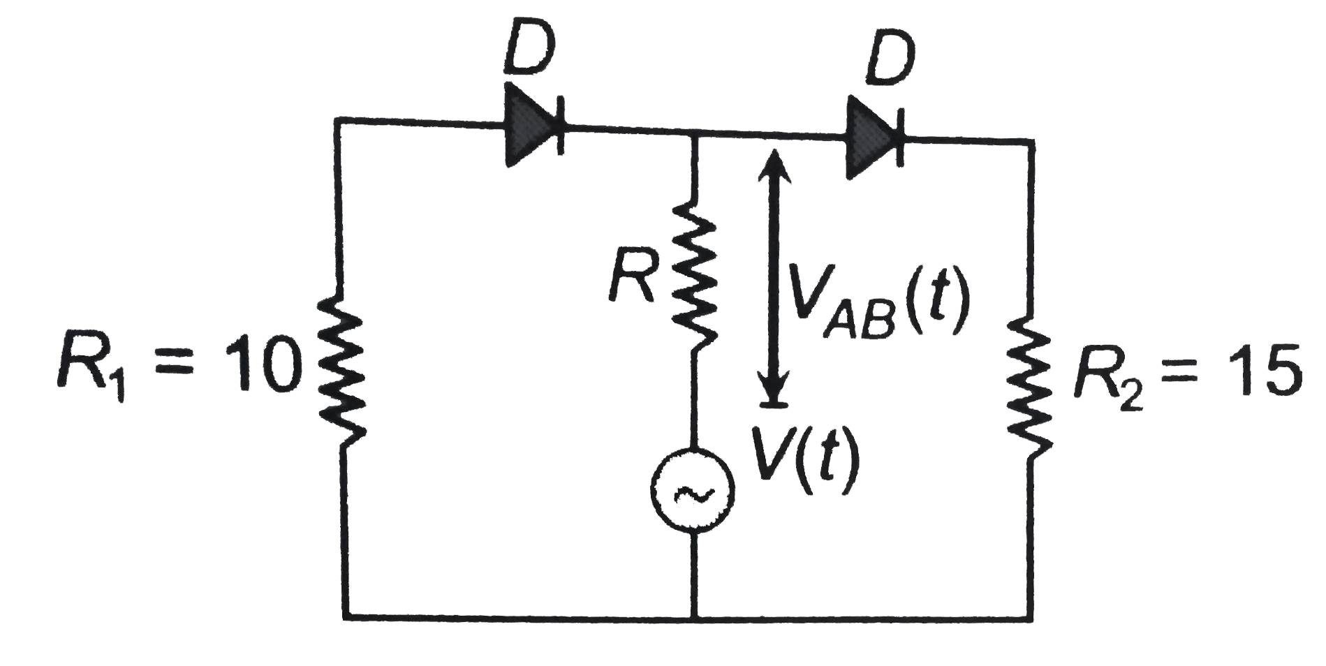 AIs half wave rectifiedBIs full wave rectifiedCHas the same peak value in the positive and negative half cyclesDHas different peak values during positive and negative half cycle
In the circuit given below, V(t) is the sinusoidal voltage source, voltage drop VAB(t) across the resistance R is
View SolutionThe rms value of input voltage in a full wave rectifier is 12 V determine the output voltage if a step up a transformer with ratio 1:2 is used
View SolutionIF VAandVB are the input voltages (either 5 V or 0 V) and Vo is the output voltage then the two gates represented in the following circuits (A) and (B) are :

View Solutionthe voltage across the capacitor, which is equal to V, is kept constant in the process.
View SolutionIf the input voltage Vi to the circuit below is given by Vi(t)=Acos(2πft), the output voltage is given by Vo(t)=Bcos(2πft+ϕ)-

Which one of the following four graphs best depict the variation of ϕ vs f ?
View Solution

