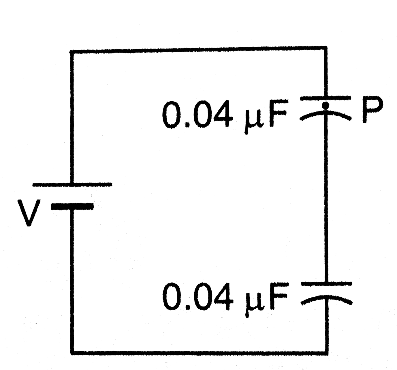
Both the capacitors shown in figure are made of square plates of edge a . The separations between the plates of the capacitors and d1 and d2 as shown in the figure. A battery of V volt and a resistance R are connected as shown in figure. At steady state an electron is projected between the plates of the lower capacitor from its lower plate along the plate as shown. Minimum speed should the electron be projected is given by 1√n(Vea2md2)1/2 so that it does not collide with any plate? Consider only the electric forces then find the value of n.

The correct Answer is:6
Topper's Solved these Questions
- CAPACITANCEBOOK - RESONANCECHAPTER - CAPACITANCEEXERCISE - Exercise - 3
26 Videos
- CAPACITANCEBOOK - RESONANCECHAPTER - CAPACITANCEEXERCISE - High Level Problems
16 Videos
- CAPACITANCEBOOK - RESONANCECHAPTER - CAPACITANCEEXERCISE - Exercise - 1
79 Videos
- ATOMIC PHYSICSBOOK - RESONANCECHAPTER - ATOMIC PHYSICSEXERCISE - Advanved level problems
17 Videos
- COMMUNICATION SYSTEMSBOOK - RESONANCECHAPTER - COMMUNICATION SYSTEMSEXERCISE - Exercise 3
13 Videos
Similar Questions
Both the capacitors shown in figure are made of square plates of edge a. The separatiopn between the plates of the capacitors are d1andd2 as shown in the figure. A potential difference V is applied between the points a and b. An electron is projected between the plates of the upper capacitor along the central line. With what minimum speed should the electron be projected so that it does not collide with any plate ? Consider only the electric forces.
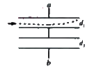
View SolutionBoth the cacpacitors shown in figure are made ofsquare of edge a The separations between the plates of the capacitors are d_1and d_2as shown in the figure A potential difference V is applied between the point a and b .An electron is projected between the plate s of the upper capacitor along the central line . With what minimum speed should the electron be projected so that it is does not collide with any plate ? consider only the electric forces.
View Solution
Knowledge Check
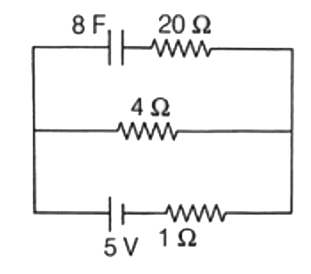
A capacitor of 8 F is connected as shown in the figure. At steady state Charge on the plates of the capacitor
 A32 CB40 CC0 CD80 C
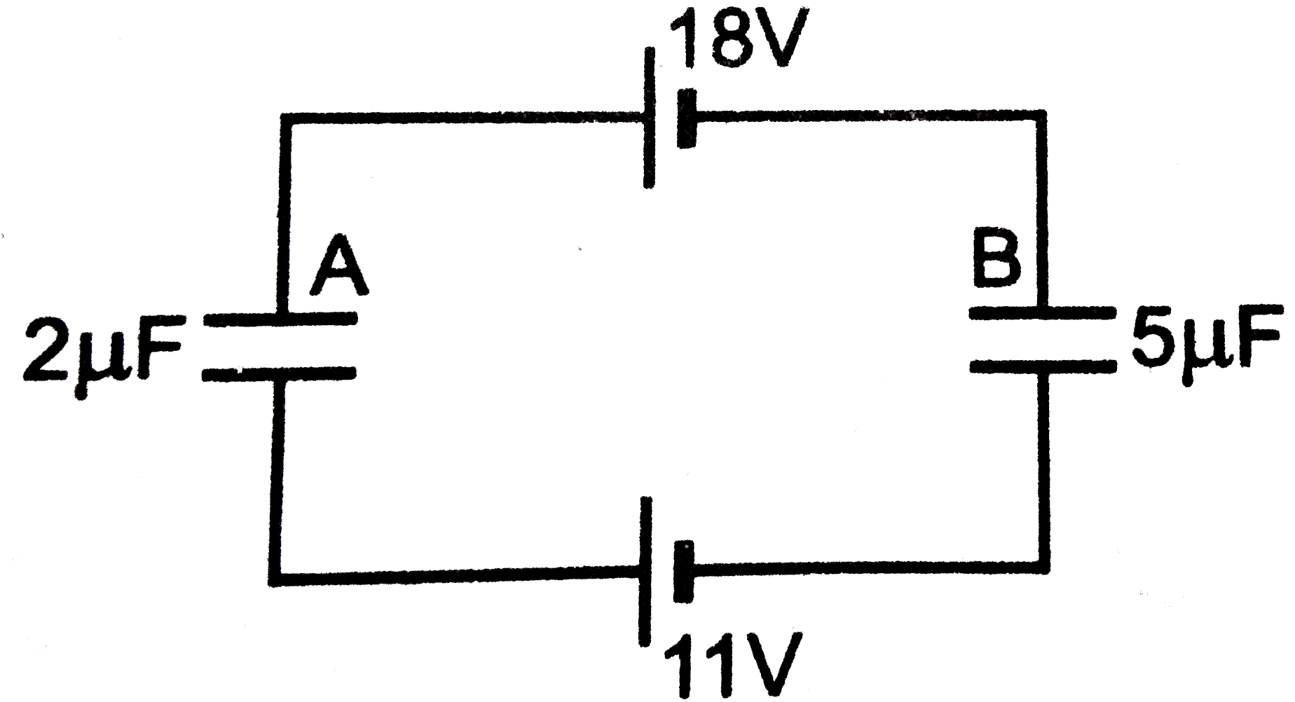
Two capacitors A and B of capacitances 2μF and 5μF are connected to two battery as shown in figure The potential difference in volt between the plate of A is
 A2B5C7D18
The potential difference between points A and B is
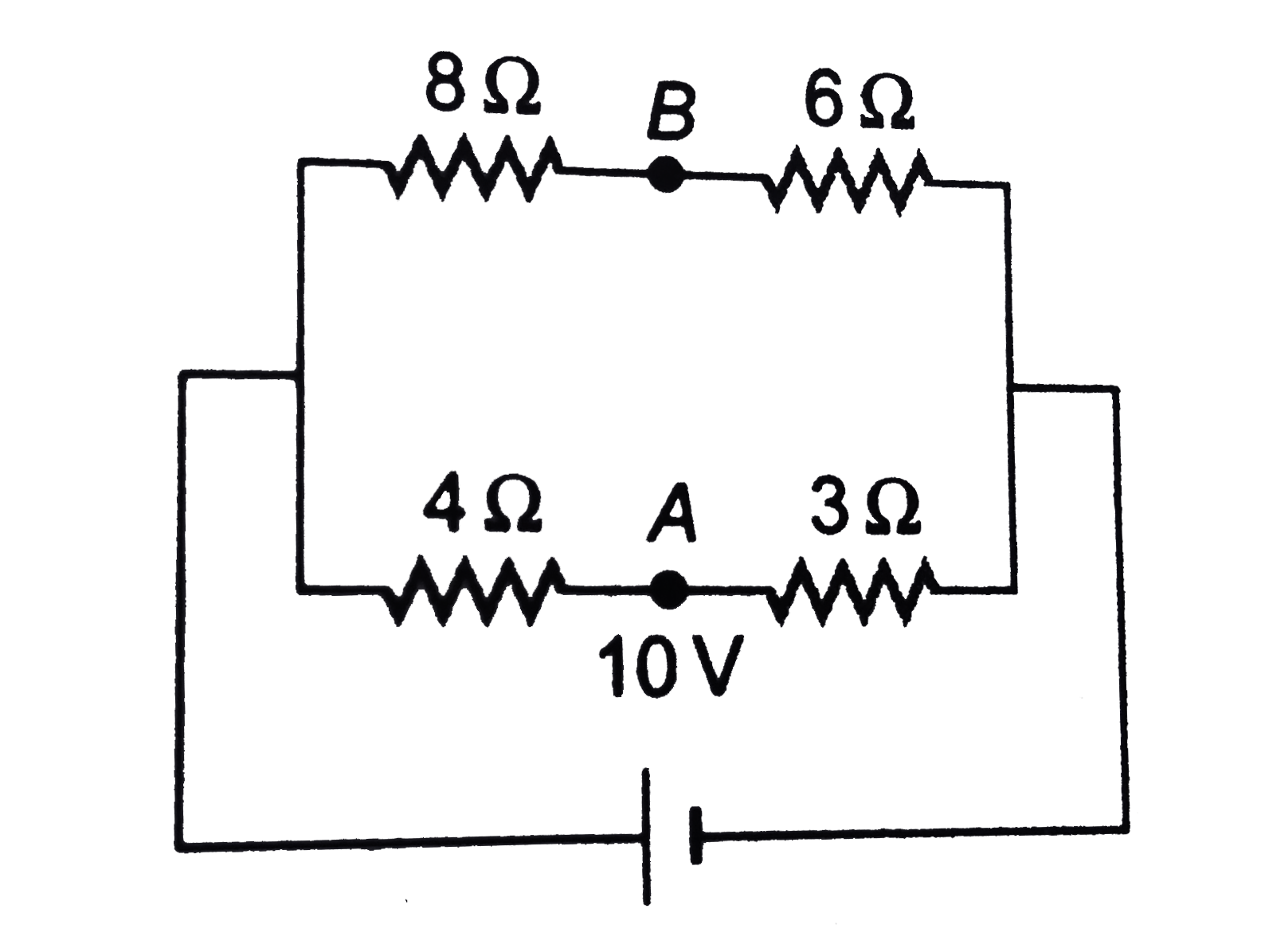 A2B5C11D18
A capacitor of 8 F is connected as shown in the figure. At steady state Charge on the plates of the capacitor

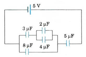
View SolutionFive capacitors are connected across a battery of 5V as shown in figure (o). Calculate the potential difference across the plates of the 5μF capacitor.
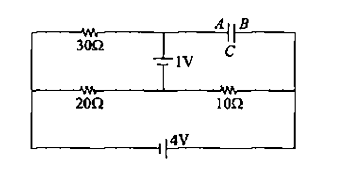
View SolutionFind the potential difference between the plates of the capacitor C in the circuit shown in figure-3.161 in steady state. The internal resistances of the cells are negligible.
View SolutionA sheet of aluminium foil of negligible thickness is placed between the plates of a capacitor of capacitance C as shown in the figure, the capacitance of capacitor becomes
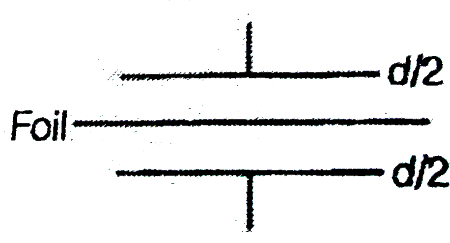
View SolutionA sheet of aluminium foil of negligible thickness is placed between the plates of a capacitor of capacitance C as shown in the figure then capacitance of capacitor becomes

View Solution
