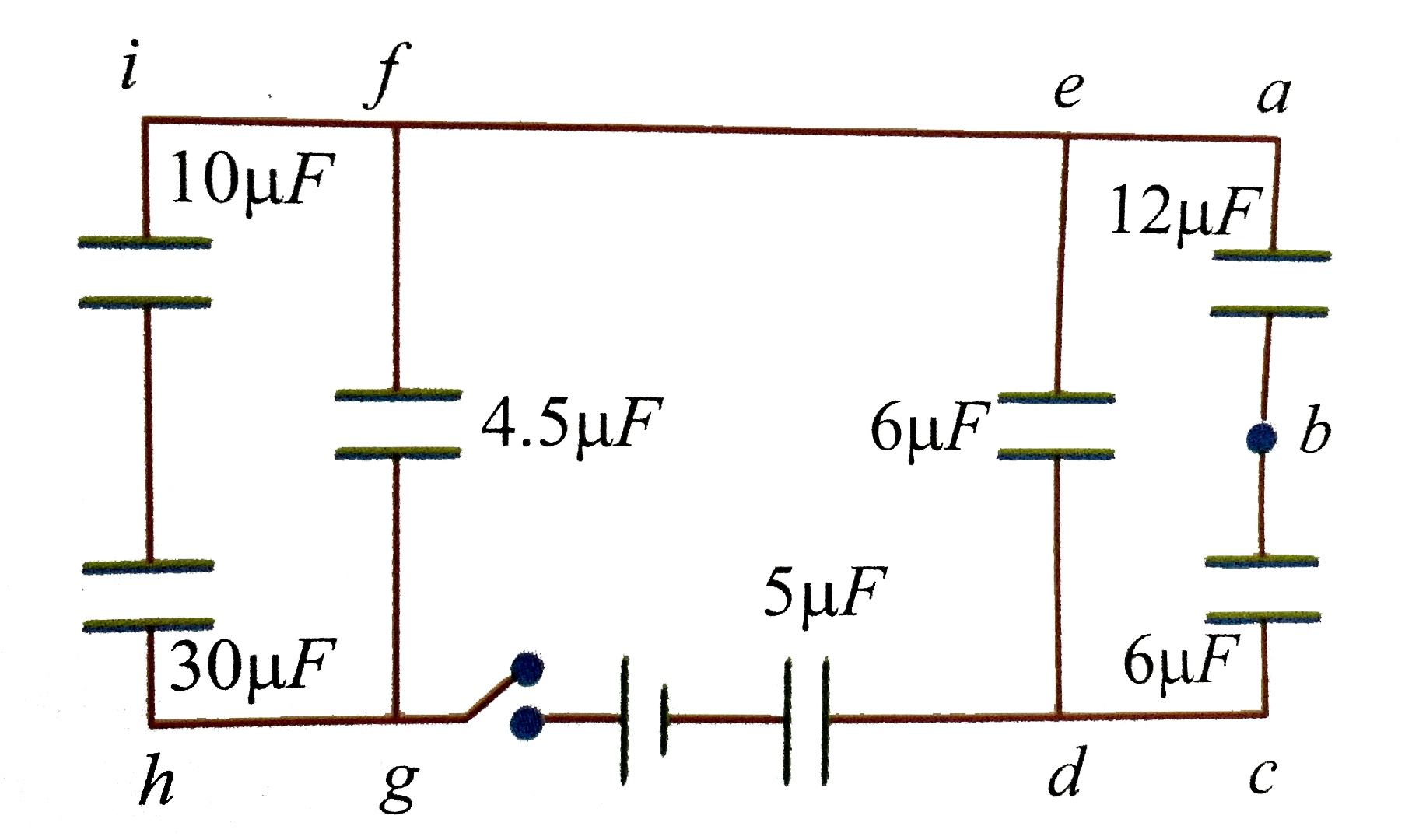
Five capacitors are connected as shown in the figure. Initially S is opened and all the capacitors are uncharged . When S is closed and steady state is obtained. Then find out potential difference between the points A and B in volt.
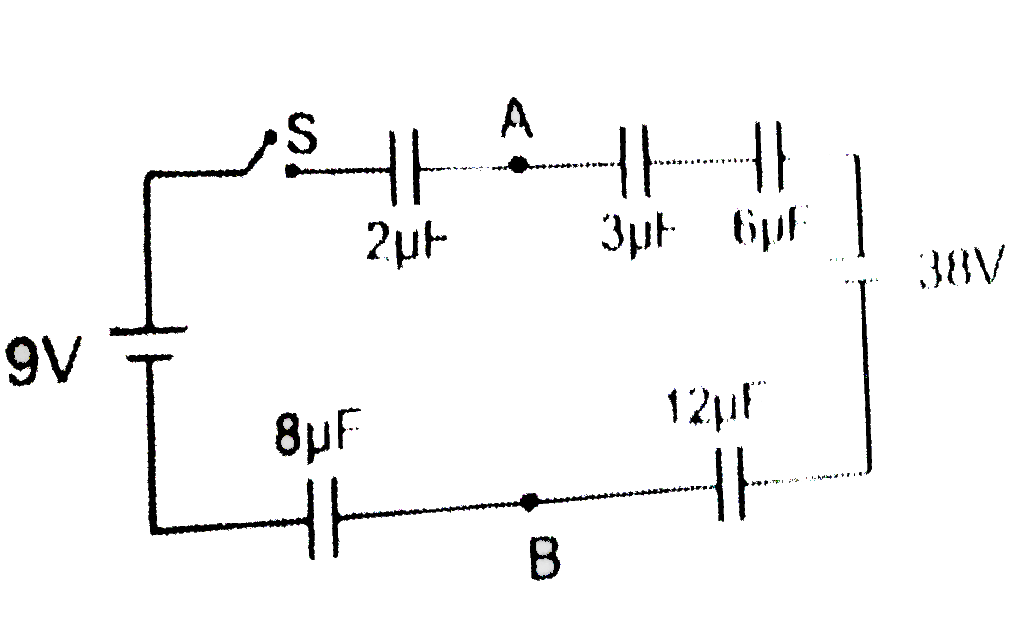
The correct Answer is:24
Step by step video, text & image solution for Five capacitors are connected as shown in the figure. Initially S is opened and all the capacitors are uncharged . When S is closed and steady state is obtained. Then find out potential difference between the points A and B in volt. by Physics experts to help you in doubts & scoring excellent marks in Class 12 exams.
Topper's Solved these Questions
- BOOK - RESONANCECHAPTER - CAPACITANCEEXERCISE - Exercise - 326videos
CAPACITANCE
- BOOK - RESONANCECHAPTER - CAPACITANCEEXERCISE - High Level Problems16videos
CAPACITANCE
- BOOK - RESONANCECHAPTER - CAPACITANCEEXERCISE - Exercise - 179videos
CAPACITANCE
- BOOK - RESONANCECHAPTER - ATOMIC PHYSICSEXERCISE - Advanved level problems17videos
ATOMIC PHYSICS
- BOOK - RESONANCECHAPTER - COMMUNICATION SYSTEMSEXERCISE - Exercise 313videos
COMMUNICATION SYSTEMS
Similar Questions
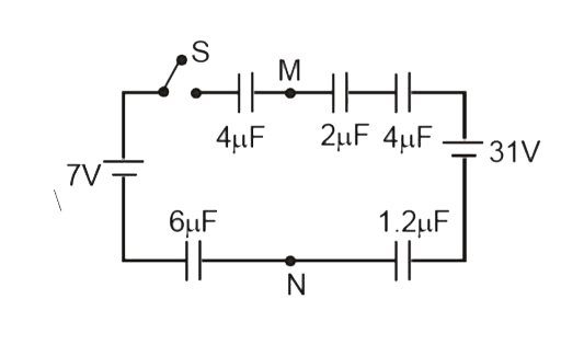
Five capacitors are connected as shown in the figure. Initially S is opened and all capacitors are uncharged. When S is closed, steady state is obtained. Then find out potential difference between the points M and N.
 View Solution
Five capacitors are connected as shown in figure. Find the equivalent capacitance between points A and B.
 View Solution
Knowledge Check
- Question 1 - Select One
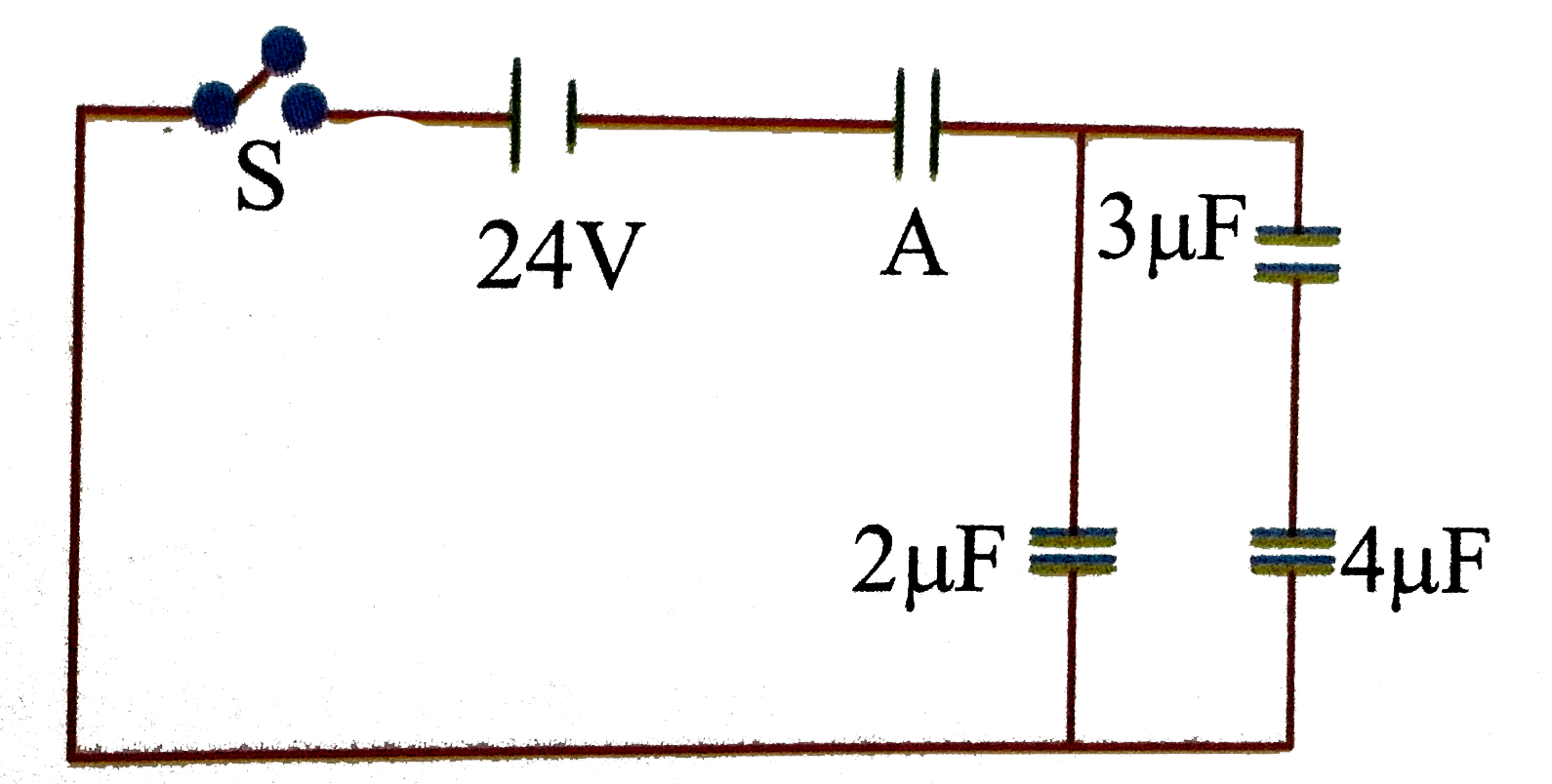
Four capacitor and a battery of emf24V are connected as shown in the figure. Initially, S is open and the capacitors are uncharged. After S is closed and steady state is attained, the potential difference across the 4μf capacitor is 7.5V. The capacitance in μf of the capacitor A is.
 .A5B7C8D10
 - Question 2 - Select One
In the circuit shown in figure potential difference between the points A and B in the steady state is
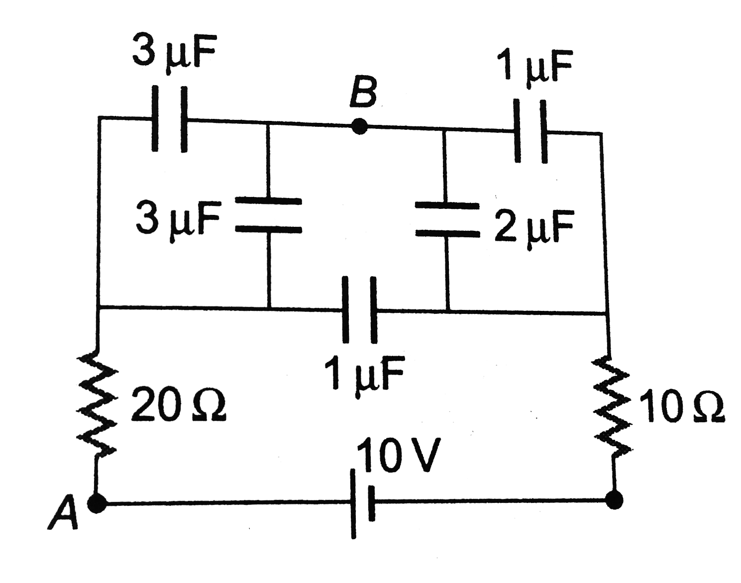 AzeroB6VC4VD103V
 - Question 3 - Select One
A capacitor of 8 F is connected as shown in the figure. At steady state Charge on the plates of the capacitor
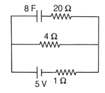 A32 CB40 CC0 CD80 C
In the circuit diagram shown here seven capacitors are connected to a source of emf E. Initially, the switch S is closed and steady state attained. Now, the potential difference between the points 'a' and 'b' is 4 volt. Now, answer the following :
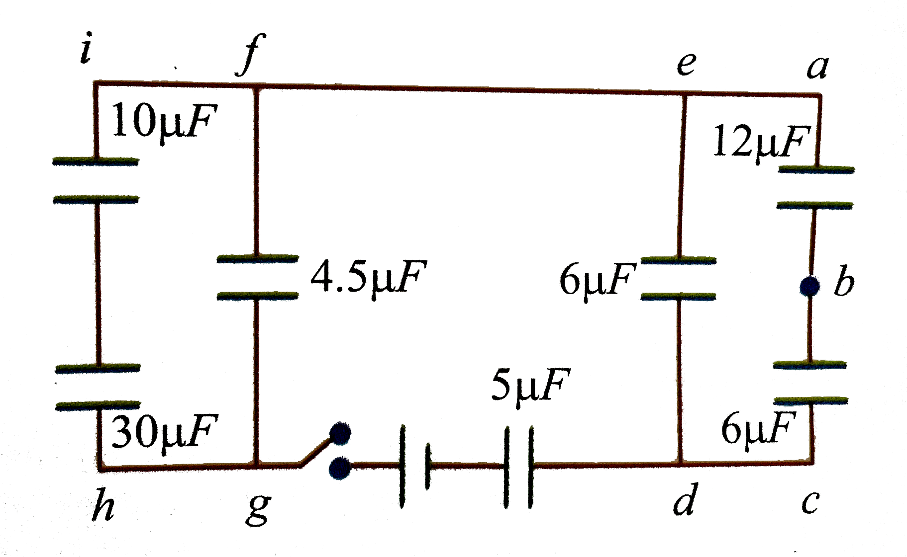 .
.
The charge on 12μF is :View SolutionIn the circuit diagram shown here seven capacitors are connected to a source of emf E. Initially, the switch S is closed and steady state attained. Now, the potential difference between the points 'a' and 'b' is 4 volt. Now, answer the following :
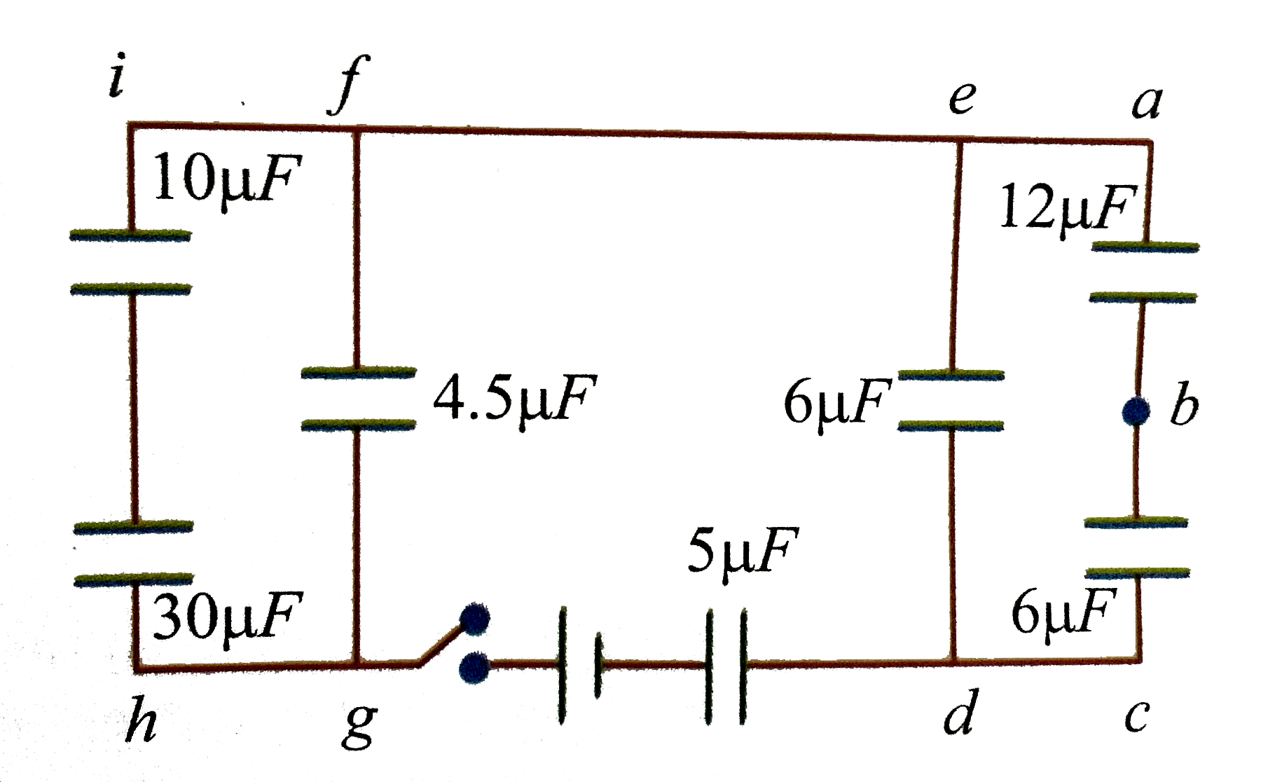 .
.
The charge on 4.5μF is :View SolutionIn the circuit diagram shown here seven capacitors are connected to a source of emf E. Initially, the switch S is closed and steady state attained. Now, the potential difference between the points 'a' and 'b' is 4 volt. Now, answer the following :
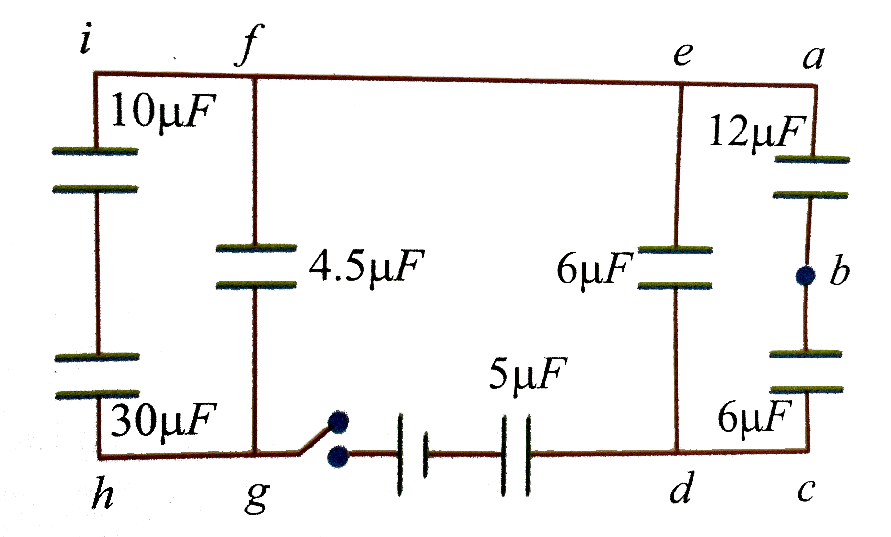 .
.
The charge on 5μC is :View SolutionIn the circuit diagram shown here seven capacitors are connected to a source of emf E. Initially, the switch S is closed and steady state attained. Now, the potential difference between the points 'a' and 'b' is 4 volt. Now, answer the following :
 .
.
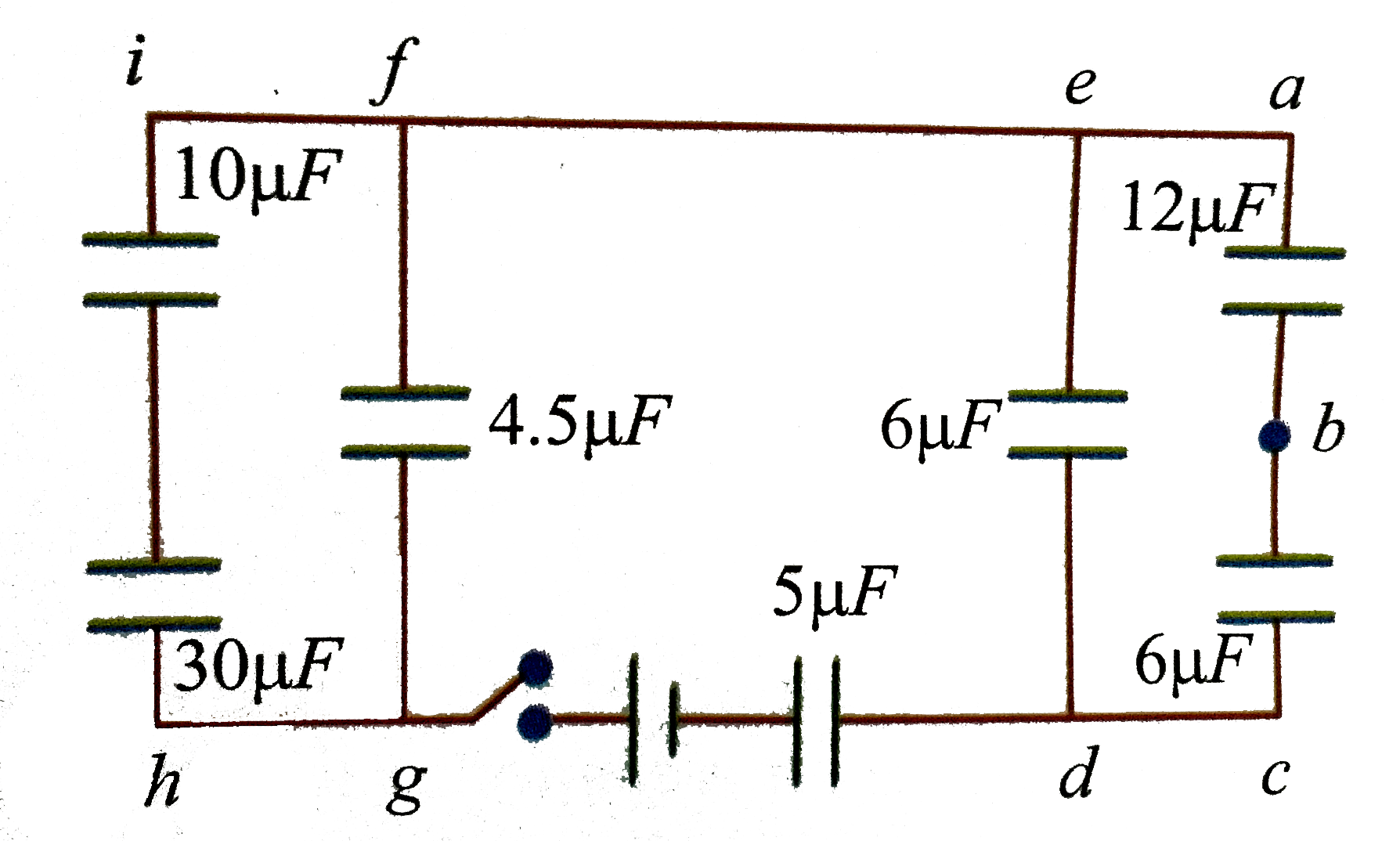
The emf E of the battery is :View SolutionIn the circuit diagram shown here seven capacitors are connected to a source of emf E. Initially, the switch S is closed and steady state attained. Now, the potential difference between the points 'a' and 'b' is 4 volt. Now, answer the following :
 .
.
The charge on 10μF is :View Solution

