In the circuit shown in figure, R(1)=1Ω,R2=2Ω,C1=1μF,C2=2μF and E=6V. Calculate charge on each capacitor in steady state
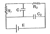
q1=2μC,q2=12μC
Topper's Solved these Questions
- CURRENT ELECTRICITYBOOK - FIITJEECHAPTER - CURRENT ELECTRICITYEXERCISE - ASSIGNMENT PROBLEMS (SUBJECTIVE)(Level-II//III)
14 Videos
- CURRENT ELECTRICITYBOOK - FIITJEECHAPTER - CURRENT ELECTRICITYEXERCISE - ASSIGNMENT PROBLEMS (OBJECTIVE)(Level-1)
45 Videos
- CURRENT ELECTRICITYBOOK - FIITJEECHAPTER - CURRENT ELECTRICITYEXERCISE - Matrix Match type
3 Videos
- COLLISION BOOK - FIITJEECHAPTER - COLLISION EXERCISE - (NUMERICAL BASED QUESTIONS)
4 Videos
- ELASTICITY AND WAVES BOOK - FIITJEECHAPTER - ELASTICITY AND WAVES EXERCISE - Assignment Problems (Objective) Level-II
15 Videos
Similar Questions
In the circuit shown in fig. R1=10Ω,R2=Ω,C1=1μF,C2=2μF, and E =6V. Calculate the charge on each capactor in the stedy state.
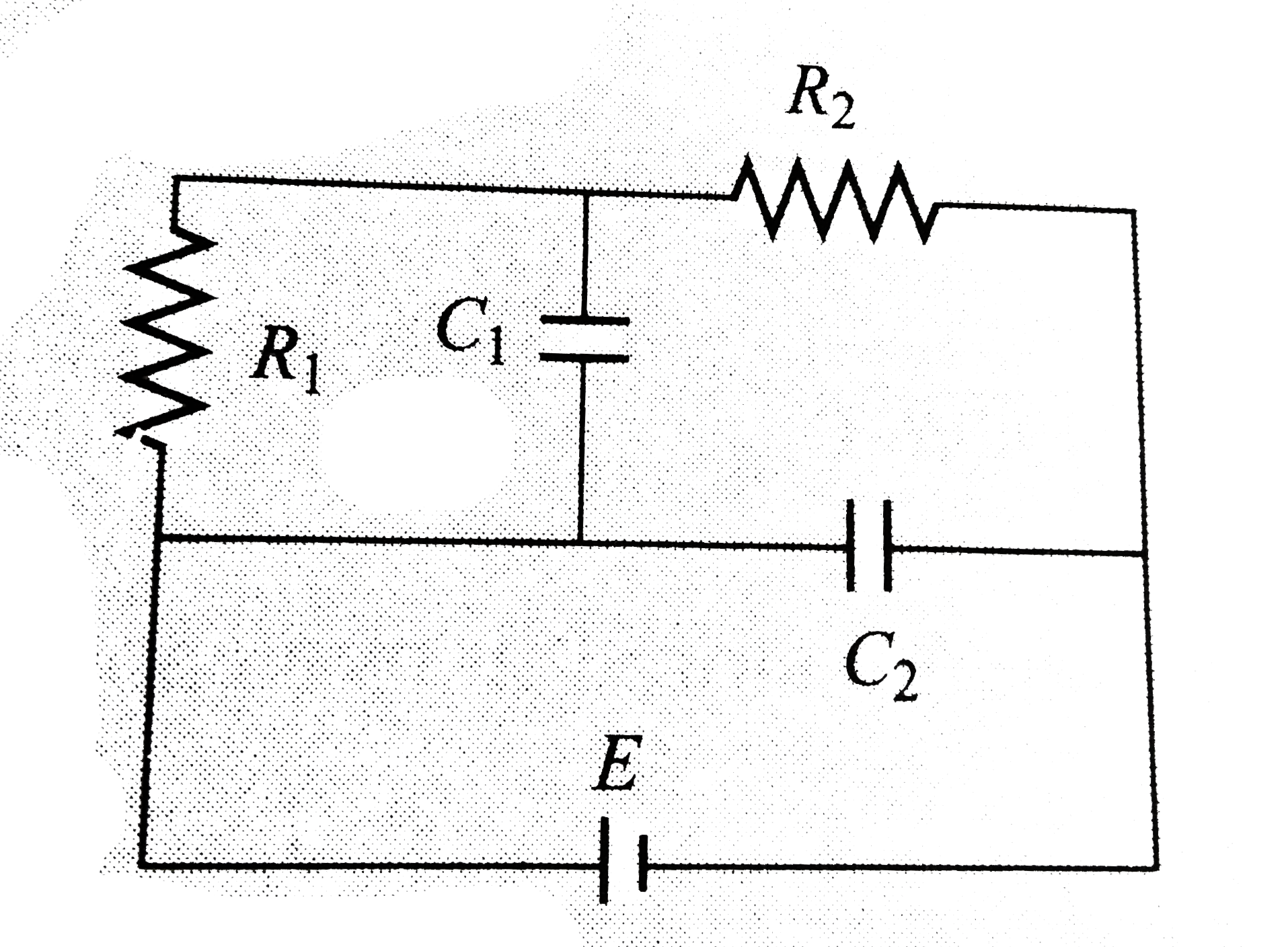
View SolutionIn the circuit shown in figure R1=R1=6R3=300MΩ,C=0.01μF and E−10V. The switch is closed at t=0, find
(a) Charge on capacitor as a function of time
(b) enegry of the capacitor at t=20s
View Solution
Knowledge Check
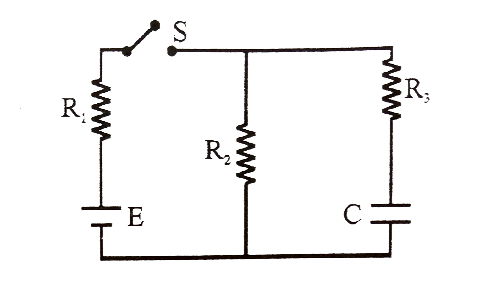
In the circuit shown in figure C1=C2=2μF. Then charge stored in
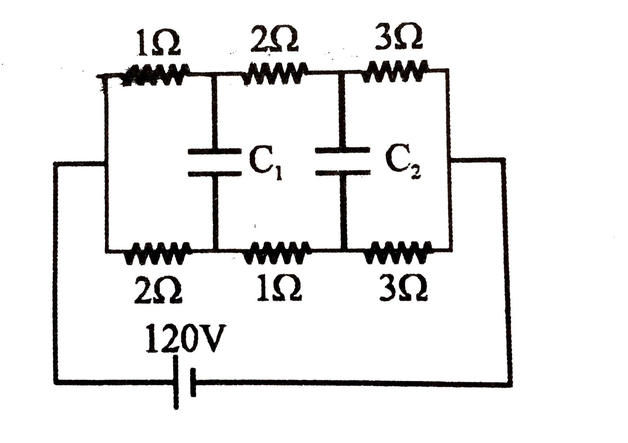 Acapacitor C1 is zeroBcapacitor C2 is zeroCboth capacitor is zeroDcapacitor C1 is 40μC
In the circuit shown below E1=4.0V,R1=2Ω,E2=6.0V,R2=4Ω and R3=2Ω. The current I1 is
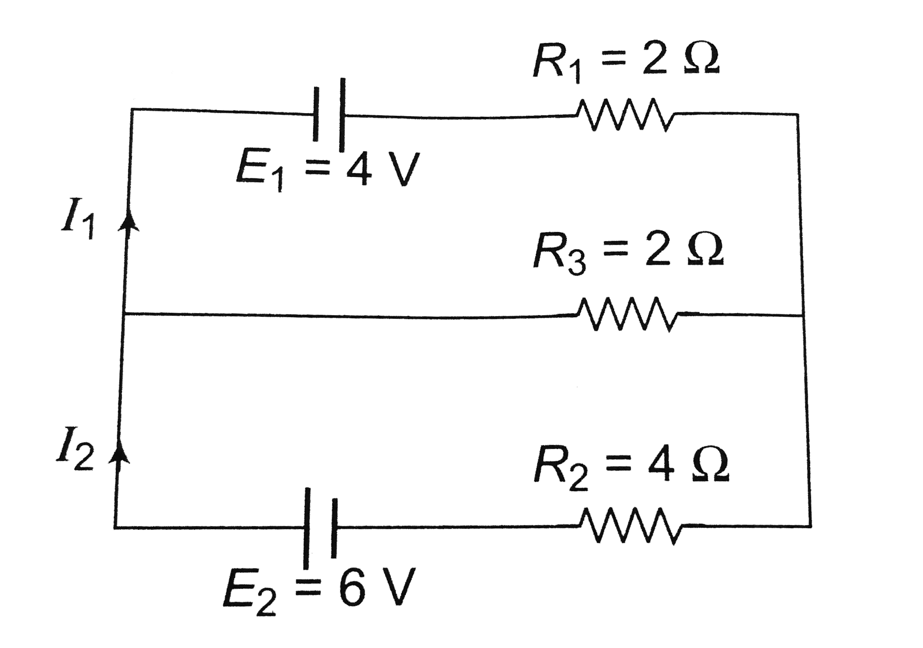 A1.6AB1.8AC1.25AD1.0A
In Fig, E=5 volt , r=1Ω,R2=4Ω,R1=R3=1Ω and C=3μF. Then the numbercal value of the charge on each plate of the capacitor is
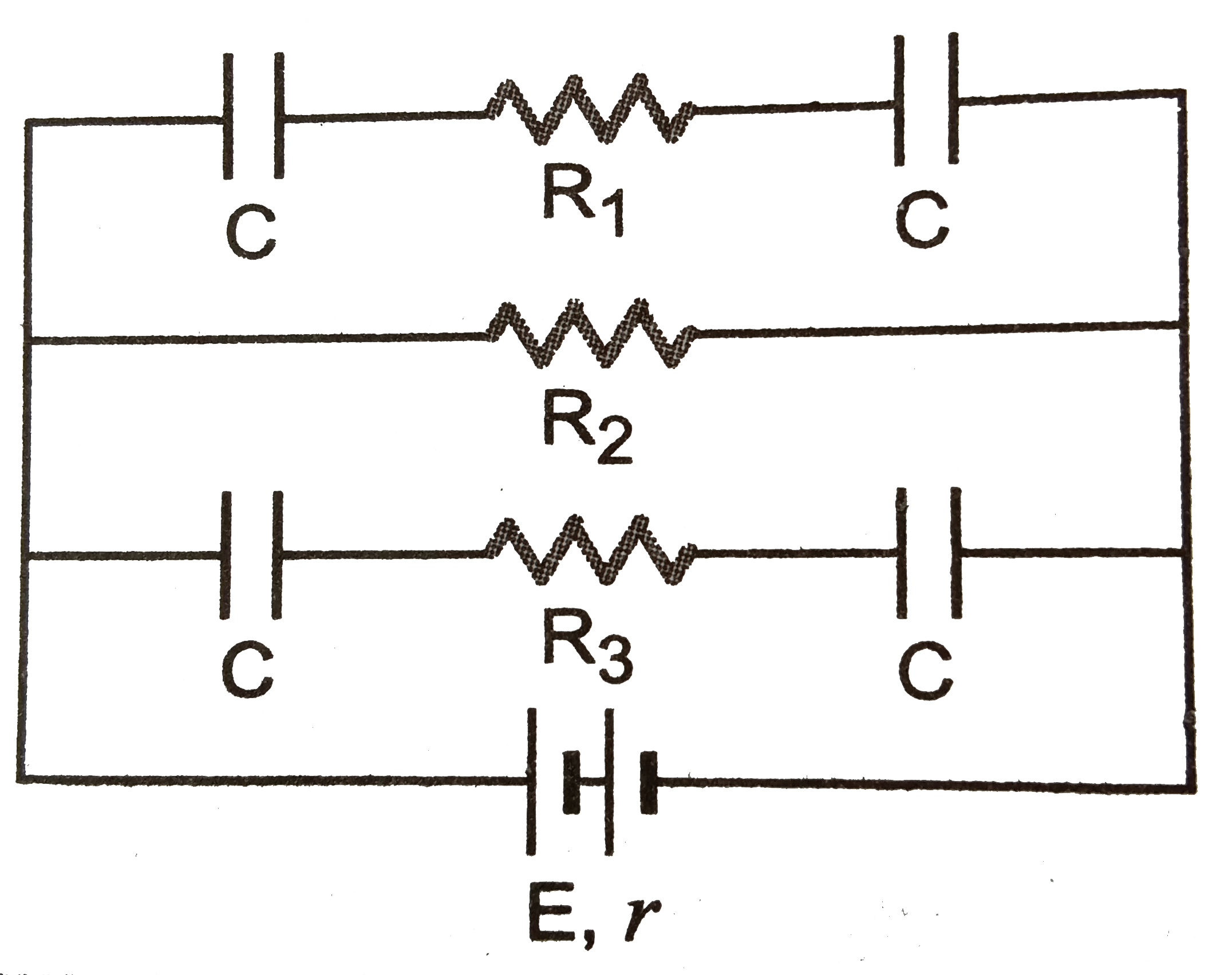 A24μCB12μCC6μCD3μC
In the circuit R1=4Ω,R2=R3=15ΩR4=30ΩandE=10V Calculate the equivalent resistance of the circuit and current in each resistor
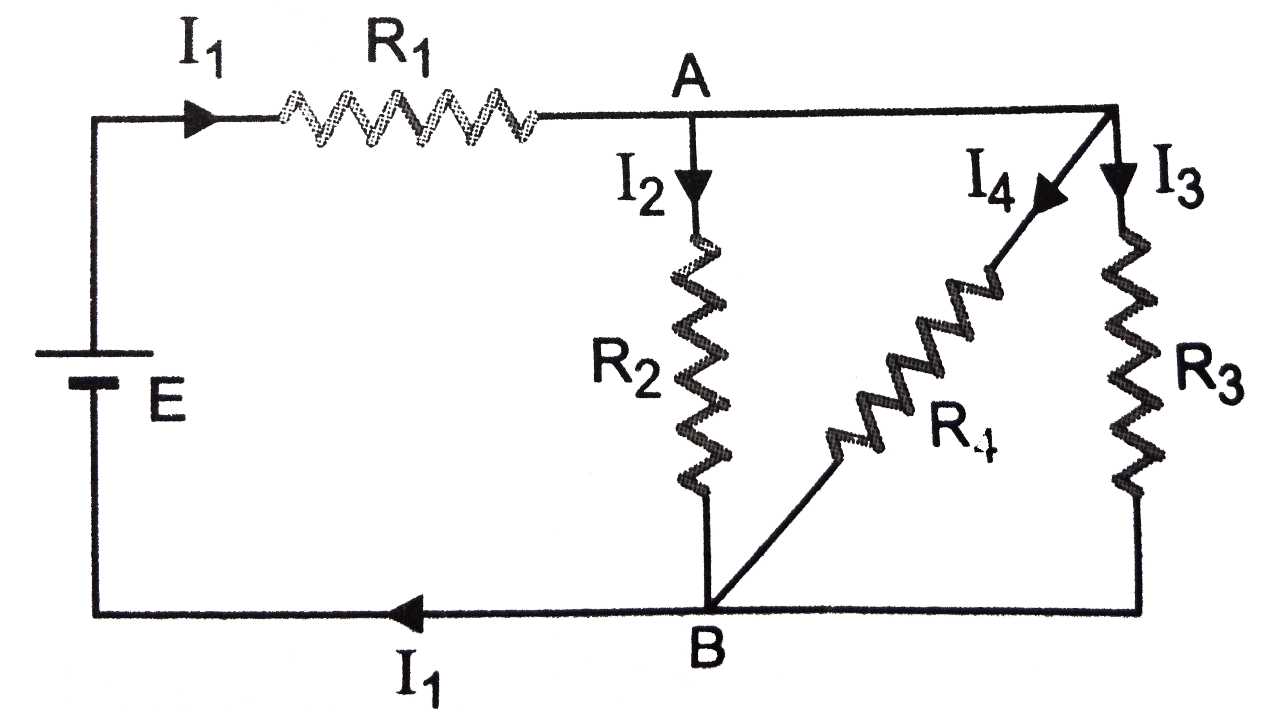
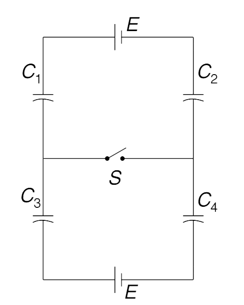
View SolutionIn the circuit shown in Figure E=12V,C1=4μF,C2=2μF,C3=6μFandC4=3μF
Find the heat produced in the circuit after switch S is shorted.
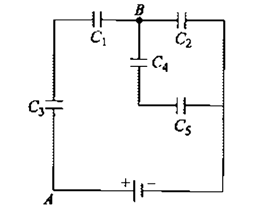
View SolutionIn the circuit shown in figure C1=5μF,C2=29μC,C3=6μF,C4=3μF and C4=7μF. If in steady state potential difference between points A and B is 11 volt, calculate potential difference across C3.
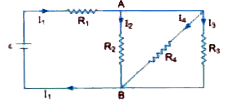
View SolutionIn the circuit shown , R1=4Ω,R2=R3=15Ω,R4=30Ω and ε=10V . Calculate the equivalent resistance of the circuit and the current in each resistor.
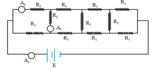
View SolutionIn the given circuit, R1 = 10Ω R2=6Omega and E = 10V, then correct statement is
View Solution
