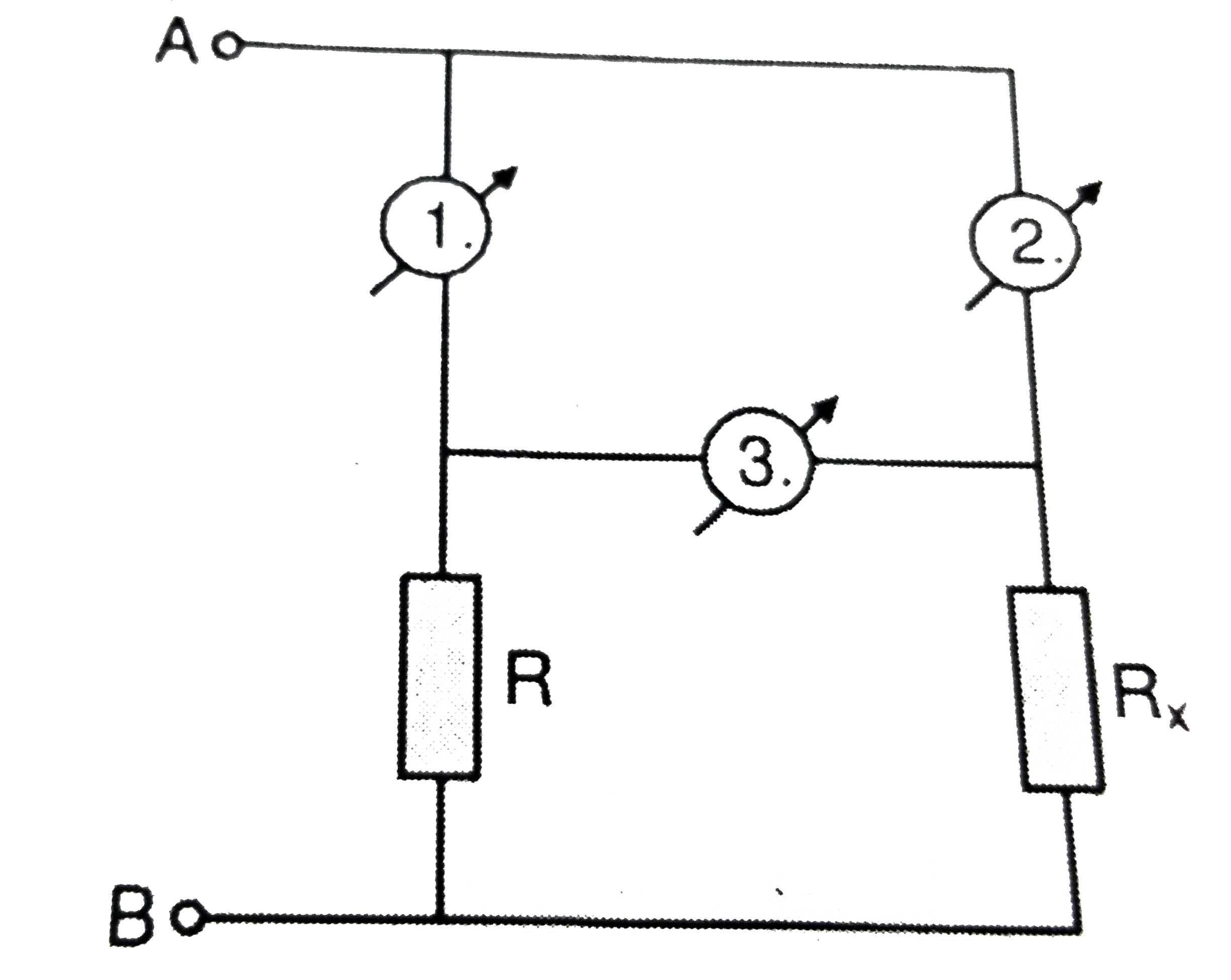
Three ammeters 1, 2, and 3 of resistances respectively are joined as shown. When some potential difference is applied across the terminals P and Q, their readings are , respectively. Then

The correct Answer is:A, B, D
Step by step video, text & image solution for Three ammeters 1, 2, and 3 of resistances R_(1). R_(2) and R_(3) respectively are joined as shown. When some potential difference is applied across the terminals P and Q, their readings are I_(1), I_(2) and I_(3), respectively. Then by Physics experts to help you in doubts & scoring excellent marks in Class 12 exams.
Updated on:21/07/2023Topper's Solved these Questions
- CURRENT ELECTRICITYBook:FIITJEEChapter:CURRENT ELECTRICITYExercise:Comprehension -(1)
Explore 5 Videos
- CURRENT ELECTRICITYBook:FIITJEEChapter:CURRENT ELECTRICITYExercise:Comprehension -2
Explore 6 Videos
- CURRENT ELECTRICITYBook:FIITJEEChapter:CURRENT ELECTRICITYExercise:ASSIGNMENT PROBLEMS (OBJECTIVE)(Level-1)
Explore 45 Videos
- COLLISION Book:FIITJEEChapter:COLLISION Exercise:(NUMERICAL BASED QUESTIONS)
Explore 4 Videos
- ELASTICITY AND WAVES Book:FIITJEEChapter:ELASTICITY AND WAVES Exercise:Assignment Problems (Objective) Level-II
Explore 15 Videos
Similar Questions
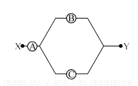
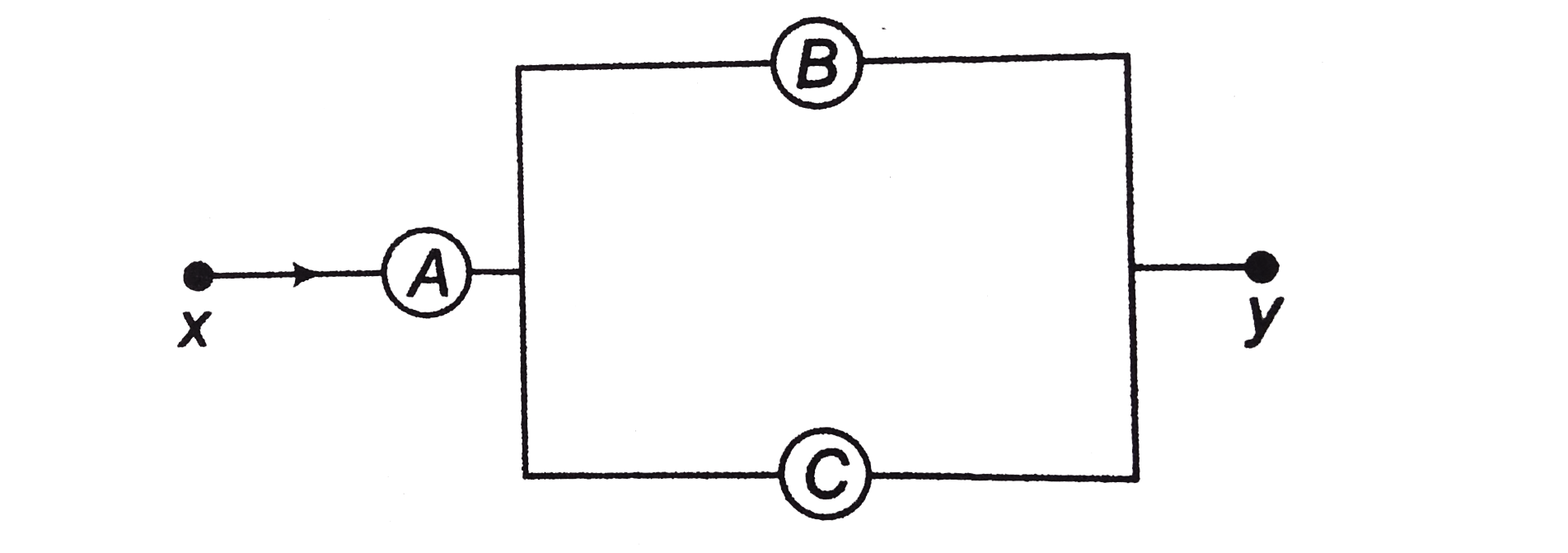
Three voltmeters A, B and C having resistances R, 1.5 R and 3 R respectively are used in a circuit as shown. When a potential difference is applied between X and Y, the readings of the voltmeters are V1,V2andV3respectively. Then :
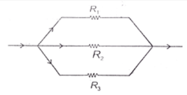
View SolutionIn the situation shown, resistance R1,R2 and R3 are in the ratio 3:2:1 , then
View Solution
Knowledge Check
Three ammeters A,B, and C of resistances RA,Rb and RC respectively are joined as shown. When some potential difference is appllied across the terminals T1 and T2 their readings are IA,IBandIC respectively Then,
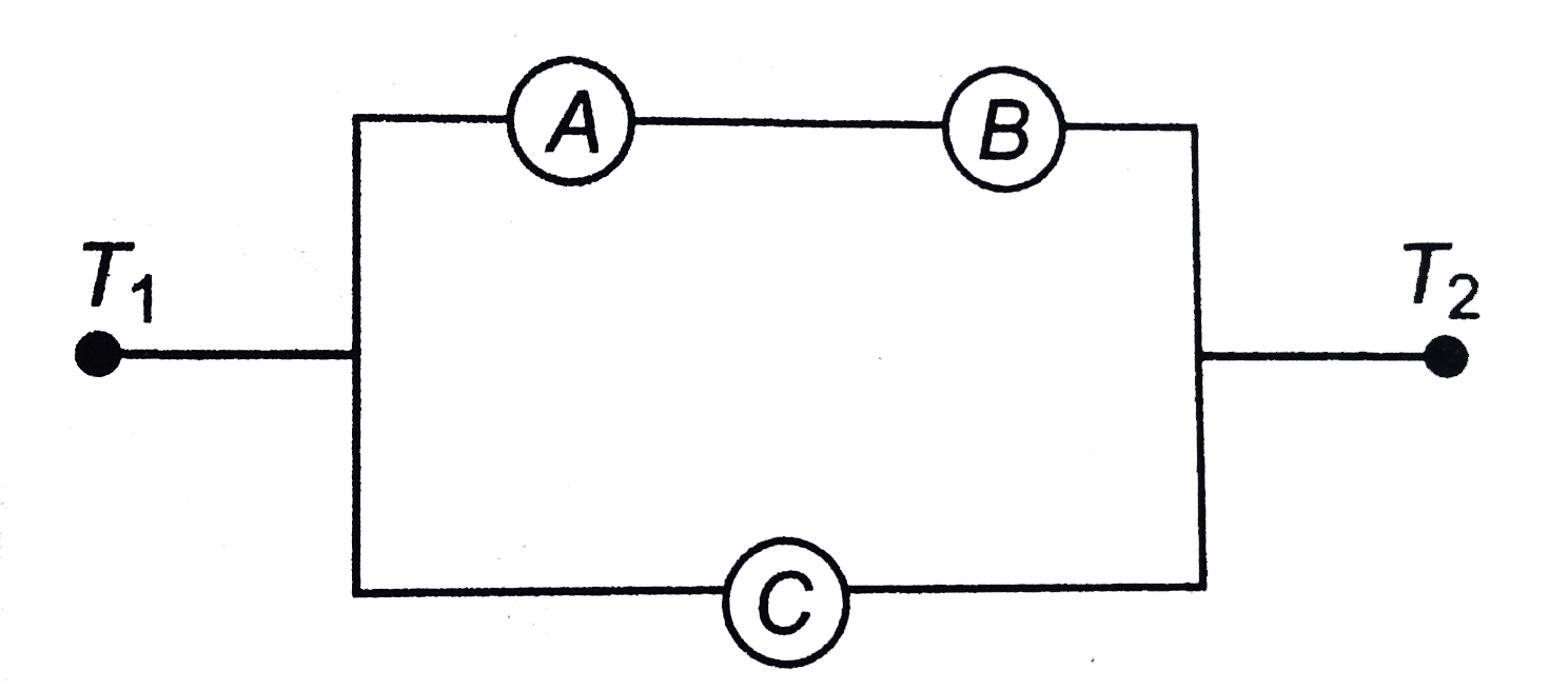 AIA=IBBIARA+IBRB=ICRCCIAIC=RCRADIBIC=RCRA+RB
Three voltmeters A, B and C having resistances R, 1.5 R and 3 R respectively are used in a circuit as shown. When a potential difference is applied between X and Y, the readings of the voltmeters are V1,V2andV3respectively. Then :
 AV1=V2=V3BV1<V2=V3CV1>V2>V3DV1>V2=V3
Three voltmeters all having different resistance, are joined as shown. When some potential difference is applied acros A and B, their readings are V1,V2 and V3. Then
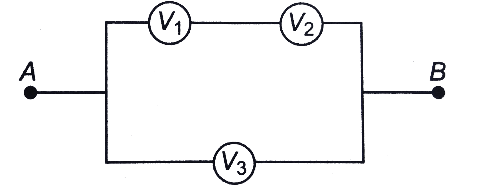 AV1=V2BV1≠V2CV1+V2=V3DV1+V2>V3
In the circit shown the three ammeters (marked as 1, 2, 3) are indentical, each have a resistance R0=2Ω. Between points A and B three is a constant potential difference of 19V. The first and second ammeter read I1=2.5 A and I2=1.5Arespectively.
(a) What is the reading of third ammeter ?
(b) Calculate value of resistance R.
( c) Investigate what happens to current I3 if the value of Rx is changed. Show approximately graphical variation of I3vsRx.
Note : Reading of ammeter implies current through brance of ammeter.
View SolutionA,B and C are voltmeters of resistance R, 1.5 R and 3R respectively as shown in the figure. When some potential difference is applied between X and Y, the voltmeter reading are VA,VBandVC respectively.
View SolutionA,B and C are voltmeters of resistances R,1.5R and 3R respectively. When some potential difference is applied between x and y the voltmeter readings are VA,V_BandV_C, then
View SolutionTwo cells of emf 3V and 5V and internal resistance r1 and r2 respectively are in series with an external resistance R. if the p.d. across 1 st cell is zero, then R is
View SolutionIn the circuit shown in the given figure, the resistances R1andR2 are respectively

View Solution