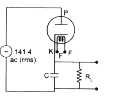
An alternating voltage of 141.4 V (rms) is applied to a vacuum diode as shown in the figure. The maximum potential difference across the condenser will be
 Solution in Kannada
100V
200V
100√2V
200√2V
The correct Answer is:B
Vpeak=√2Vrms=√2×141.4=200V
Topper's Solved these Questions
- BOOK - MODERN PUBLICATIONCHAPTER - SOLIDS & SEMICONDUCTOR DEVICESEXERCISE - Multiple Choice Questions - LEVEL -III (Questions From AIEEE/JEE Examination)9videos
SOLIDS & SEMICONDUCTOR DEVICES
- BOOK - MODERN PUBLICATIONCHAPTER - SOLIDS & SEMICONDUCTOR DEVICESEXERCISE - Recent Competitive Questions26videos
SOLIDS & SEMICONDUCTOR DEVICES
- BOOK - MODERN PUBLICATIONCHAPTER - SOLIDS & SEMICONDUCTOR DEVICESEXERCISE - Multiple Choice Questions - LEVEL -I (PARAGRAPH)6videos
SOLIDS & SEMICONDUCTOR DEVICES
- BOOK - MODERN PUBLICATIONCHAPTER - ROTATIONAL MOTIONEXERCISE - RCQ8videos
ROTATIONAL MOTION
- BOOK - MODERN PUBLICATIONCHAPTER - TRANSFERENCE OF HEAT EXERCISE - Recent Competitive Questions4videos
TRANSFERENCE OF HEAT
Similar Questions
Statement - 1 : Sky wave signals are used for long distance radio communication. These signals are in general, less stable than ground wave signals. Statement - 2 : The state of ionosphere varies from hour to hour, day to day and season to season.
02:57View SolutionThe forbidden energy gap in Ge in 0.72 eV Given, hc=12400 eV−Å The maximum wavelength of radiation that will generate electron hole pair is
03:02View SolutionIn a triode value for a grid voltage Vg=−1.2V , the phase current Ip and plate voltage Vp are given Ip=(−5+0.1V0),Ip in mAandVp in volt . When grid voltage is changed to - 3.2 V at constant plate voltage of 150 V , a plate current of 5 mA is observed , then
Plate resistance Rp isView SolutionThe moment of inertia of a circular disc of radius 2 m and mass 1 kg about an axis passing through the centre of mass but perpendicular to the plane of the disc is 2 kg m2. Its moment of inertia about an axis parallel to this axis but passing through the edge of the disc is :
 View Solution
Two slabs are of the thicknesses d1 and d2. Their thermal conductivities are K1 and K2 respectively They are in series. The free ends of the combination of these two slabs are kept at temperatures θ1 and θ2. Assume θ1>θ2. The temperature θ of their common junction is
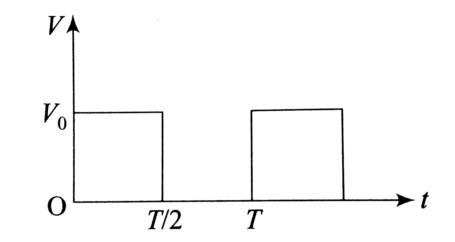
02:08View SolutionThe rms value of potential difference V shown in the figure is
 View Solution
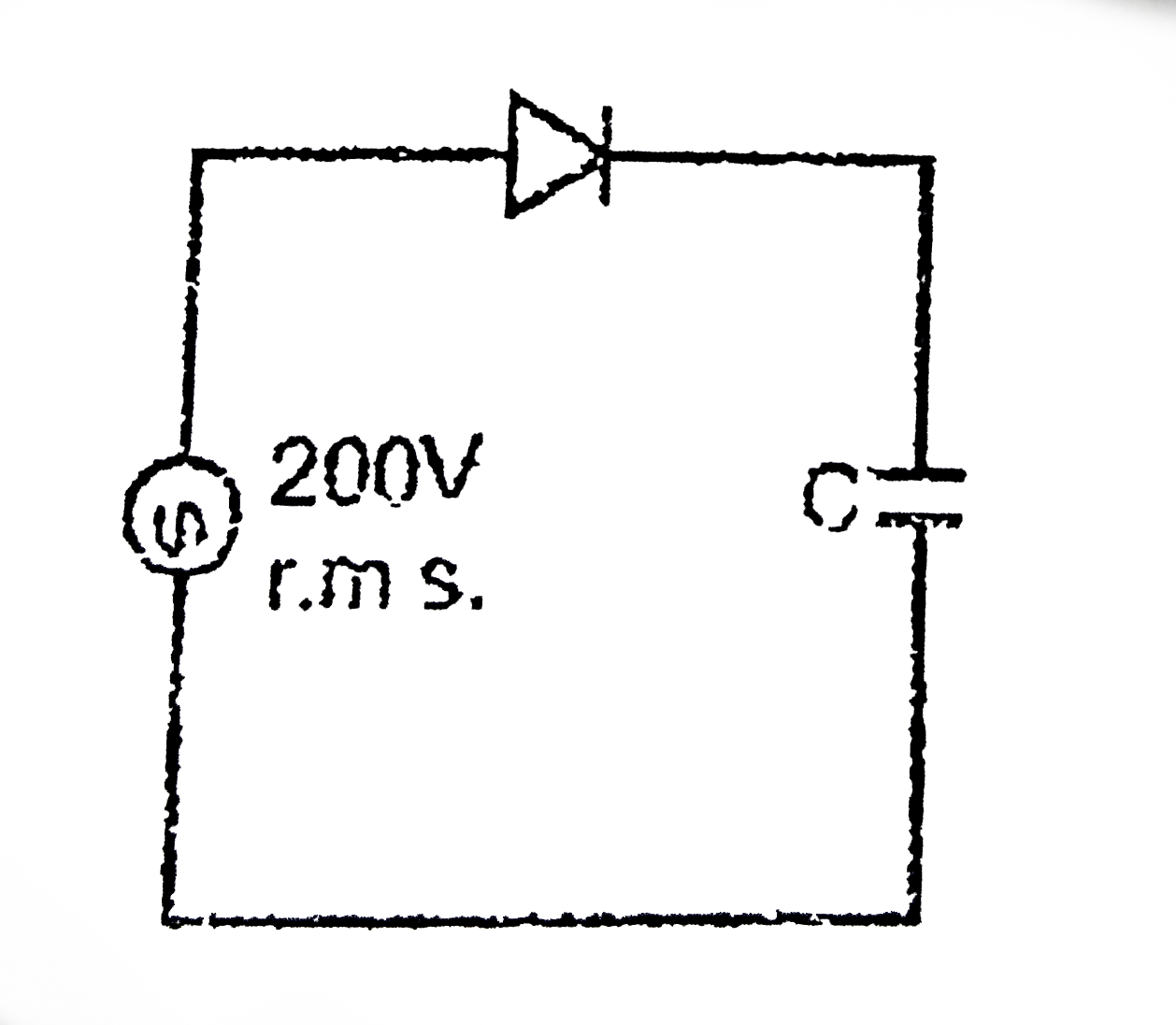
In the figure an A.C of rms voltage 200 volt is appled to the circuit containing diode and the capacitor and it is being rectified. The maximum potential across the capacitor C in volt will be03:18View SolutionAn alternating voltage of 141.4V(rms) is applied to a vacuum diode as shown in the figure. The maximum potential difference across the condenser will be
 02:57View Solution
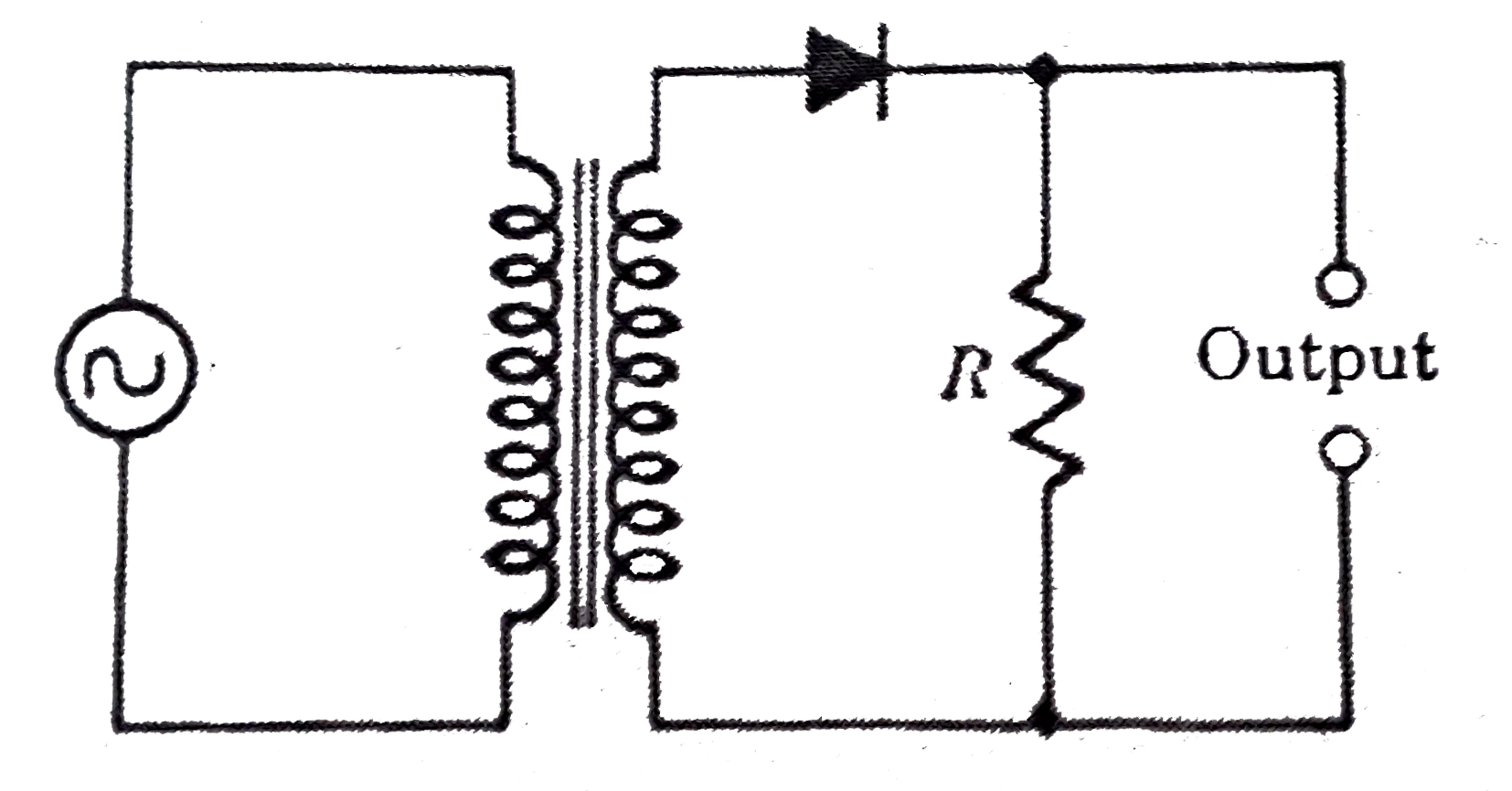
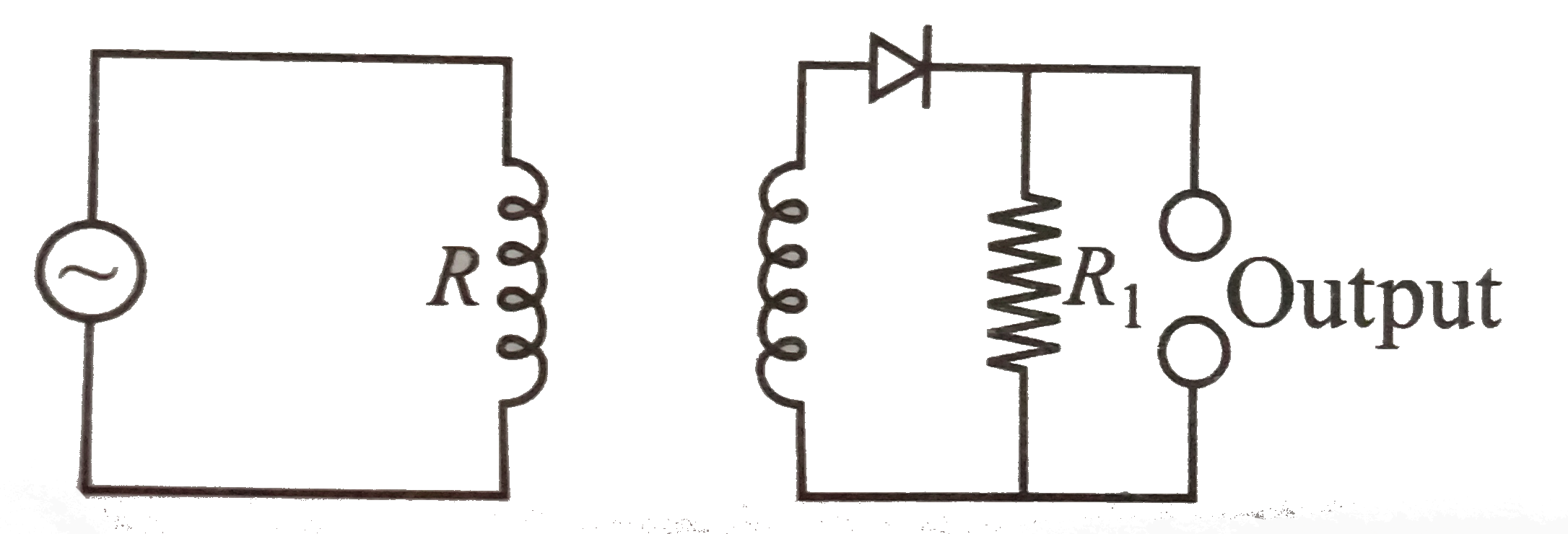
A sinusoidal voltage of rms value 220V is applied to a diode and a resistor R in the circuit shown in fig. Show that half wave rectifaction occurs. If the diode is ideal, what is the rms voltage across?
 01:30View Solution
In the circuit shown if current for the diode is 20 muA , the potential difference across the diode is
02:26View SolutionA sinusoidal voltage of rms value 220 V is applied to a diode and a resistor R in the circuit shown in figure so that half wave rectification occurs. If the diode is ideal, what is the rms voltage across R1?
 02:51View Solution
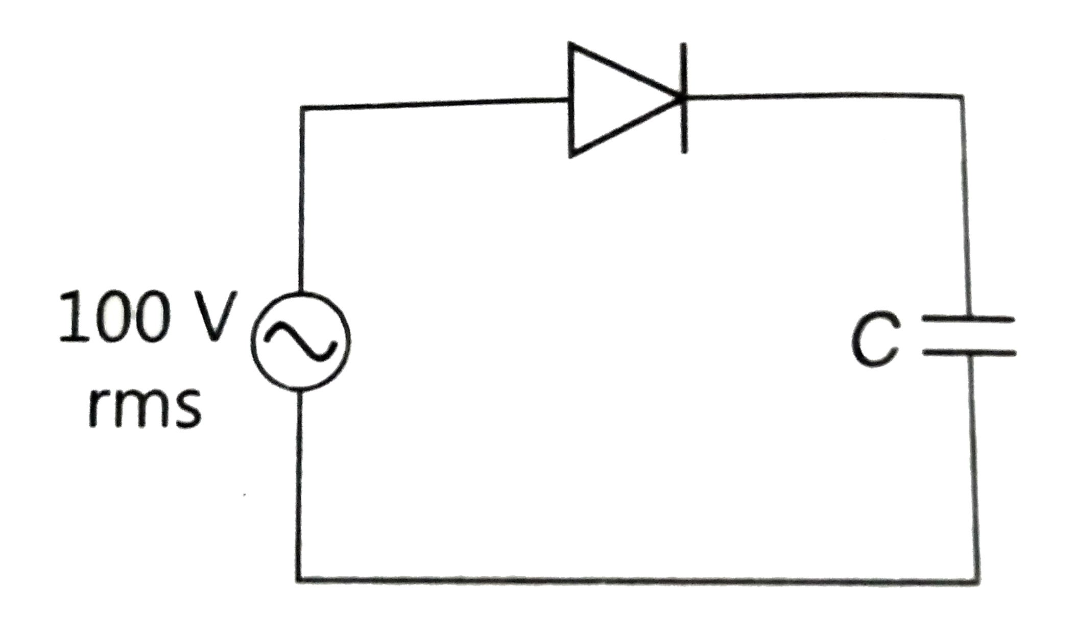
A sinusoidal voltage of rms value 100V is connected to an ideal function diode as shown in figure. The final potential difference across the capacitor will be
 03:06View Solution
If an alternating voltage is applied across a diode in series with a load, then
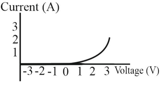
03:22View SolutionShown below is a graph of current versus applied voltage for a diode . Approximately , what is the resistance of the diode for an applied voltage of – 1 V ?
 01:08View Solution
A diode is connected to 200 V (rms) ac in series with a capacitor as shown in figure. The voltage across the capacitor is
 View Solution

