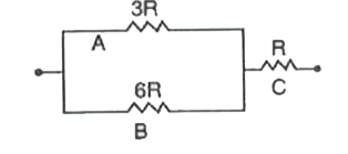
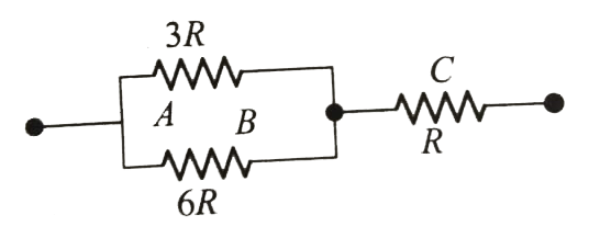
The three resistances A, B and C have values 3R, 6R and R respectively . When some potential difference is applied across the network, the thermal powers dissipated by A, B and C are is the ratio

2:3:4
2:4:3
4:2:3
3:2:4
The correct Answer is:C
Topper's Solved these Questions
Similar Questions
(a) Two heater coils made of the same material are connected in paralled across the mains. The length of diameter of one the coil is triple that of other. Which of these will produce more heat?
(b) Three equal resistors connected in series across a source of emf together dissipated 10Wa of power. What would be the power disspated if the same resistors are connected in parallel across the same source of emf?
Two resistor R1 and R2 may be connect either in series or in parellel across a battery of zero internal resistance. it is required that joule heating for the parallel combination be four times than for series combination. if R1=100Ω find R2
(d) The three resistance A,BandC have values 3R,6R and R respectively. Now some potential difference is applied across the network . Find the ratio of thermal powers dissipated between X and Y . find ratio of power consumed by A,B,andC.

View SolutionFigure 7.37 shows a network of three resistances. When some potential difference is applied across the network , thermal powers dissipated by A,BandC are in the ratio

View Solution
Knowledge Check
Figure 7.37 shows a network of three resistances. When some potential difference is applied across the network , thermal powers dissipated by A,BandC are in the ratio
 A2:3:4B2:4:3C4:2:3D3:2:4
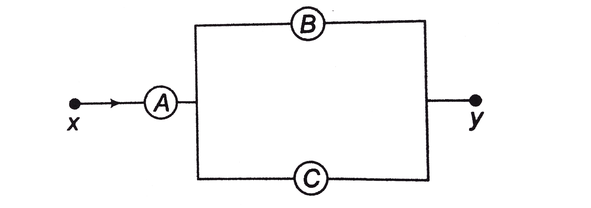
A,B and C are voltmeters of resistances R,1.5R and 3R respectively. When some potential difference is applied between x and y the voltmeter readings are VA,V_BandV_C, then
 AVA=VB=VCBVA≠VB=VCCVA=VB≡VCDVA+VB=VC
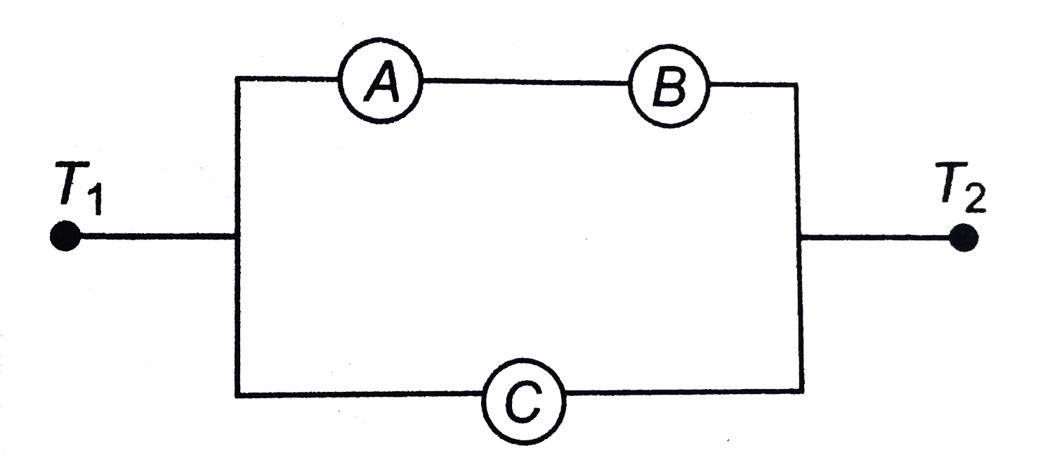
Three ammeters A,B, and C of resistances RA,Rb and RC respectively are joined as shown. When some potential difference is appllied across the terminals T1 and T2 their readings are IA,IBandIC respectively Then,
 AIA=IBBIARA+IBRB=ICRCCIAIC=RCRADIBIC=RCRA+RB
A,B and C are voltmeters of resistances R,1.5R and 3R respectively. When some potential difference is applied between x and y the voltmeter readings are VA,VBandVC, then

View SolutionA,B and C are voltmeters of resistances R,1.5R and 3R respectively. When some potential difference is applied between x and y the voltmeter readings are VA,V_BandV_C, then

View SolutionA,B and C are voltmeters of resistances R,1.5R and 3R respectively. When some potential difference is applied between x and y the voltmeter readings are VA,V_BandV_C, then

View SolutionA,B and C are voltmeters of resistances R,1.5R and 3R respectively. When some potential difference is applied between x and y the voltmeter readings are VA,V_BandV_C, then

View SolutionThree ammeters A,B, and C of resistances RA,Rb and RC respectively are joined as shown. When some potential difference is appllied across the terminals T1 and T2 their readings are IA,IBandIC respectively Then,

View Solution
