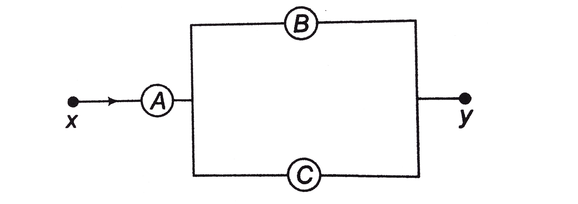
A,B and C are voltmeters of resistances R,1.5R and 3R respectively. When some potential difference is applied between x and y the voltmeter readings are VA,V_BandV_C, then
VA=VB=VC
VA≠VB=VC
VA=VB≡VC
VA+VB=VC
The correct Answer is:A
B and C are in parallel
∴VB=VC
Further RA=R
RBC=(1.5R)(3R)1.5R+3R=R
or RA=RBC
∴VA=VBC
because iRA=iRBC
Topper's Solved these Questions
- CURRENT ELECTRICITYBOOK - DC PANDEY ENGLISHCHAPTER - CURRENT ELECTRICITYEXERCISE - Level 2 More Than One Correct
10 Videos
- CURRENT ELECTRICITYBOOK - DC PANDEY ENGLISHCHAPTER - CURRENT ELECTRICITYEXERCISE - Level 2 Comprehension Example Type
2 Videos
- CURRENT ELECTRICITYBOOK - DC PANDEY ENGLISHCHAPTER - CURRENT ELECTRICITYEXERCISE - Level 1 Subjective
53 Videos
- COMMUNICATION SYSTEMBOOK - DC PANDEY ENGLISHCHAPTER - COMMUNICATION SYSTEMEXERCISE - Subjective
11 Videos
- ELECTROMAGNETIC INDUCTIONBOOK - DC PANDEY ENGLISHCHAPTER - ELECTROMAGNETIC INDUCTIONEXERCISE - Medical entrances gallery
25 Videos
Similar Questions
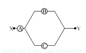
Three voltmeters A, B and C having resistances R, 1.5 R and 3 R respectively are used in a circuit as shown. When a potential difference is applied between X and Y, the readings of the voltmeters are V1,V2andV3respectively. Then :
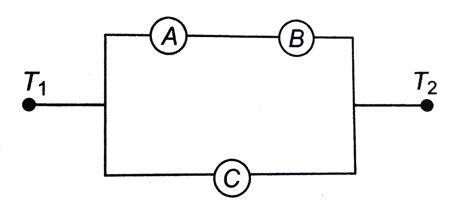
View SolutionThree ammeters A,B, and C of resistances RA,Rb and RC respectively are joined as shown. When some potential difference is appllied across the terminals T1 and T2 their readings are IA,IBandIC respectively Then,
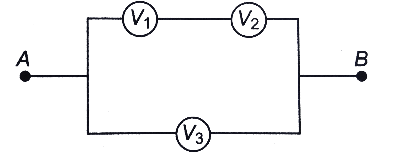
View SolutionThree voltmeters all having different resistance, are joined as shown. When some potential difference is applied acros A and B, their readings are V1,V2 and V3. Then
View SolutionIn the circuit shown some potential difference is applied between A and B. The equivalent resistance between A and B is R. Then
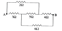
View SolutionIn the circuit shown in fig. some potential difference is applied between A and B. The equivalent resistance between A and B is R.

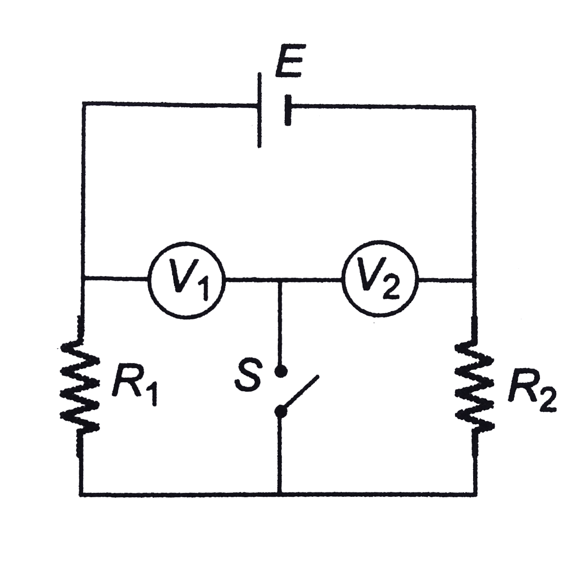
View SolutionThree voltmeters are connected as shown.

A potential difference has been applied between A and B. On closing the swich S, readings of voltmeters?
View SolutionIn the circuit shownin figure V1 and V2 are two voltmeter of resistances 3000Ω and 2000Ω respectively. In additions R1=2000Ω, R2=3000ω and E=200V then
a. Fid the reading of voltmeters V1 and V2 when
i. switch S is open
ii. Switch S is closed
b. Current through S, when it is closed (Disregard the resistance of battery)
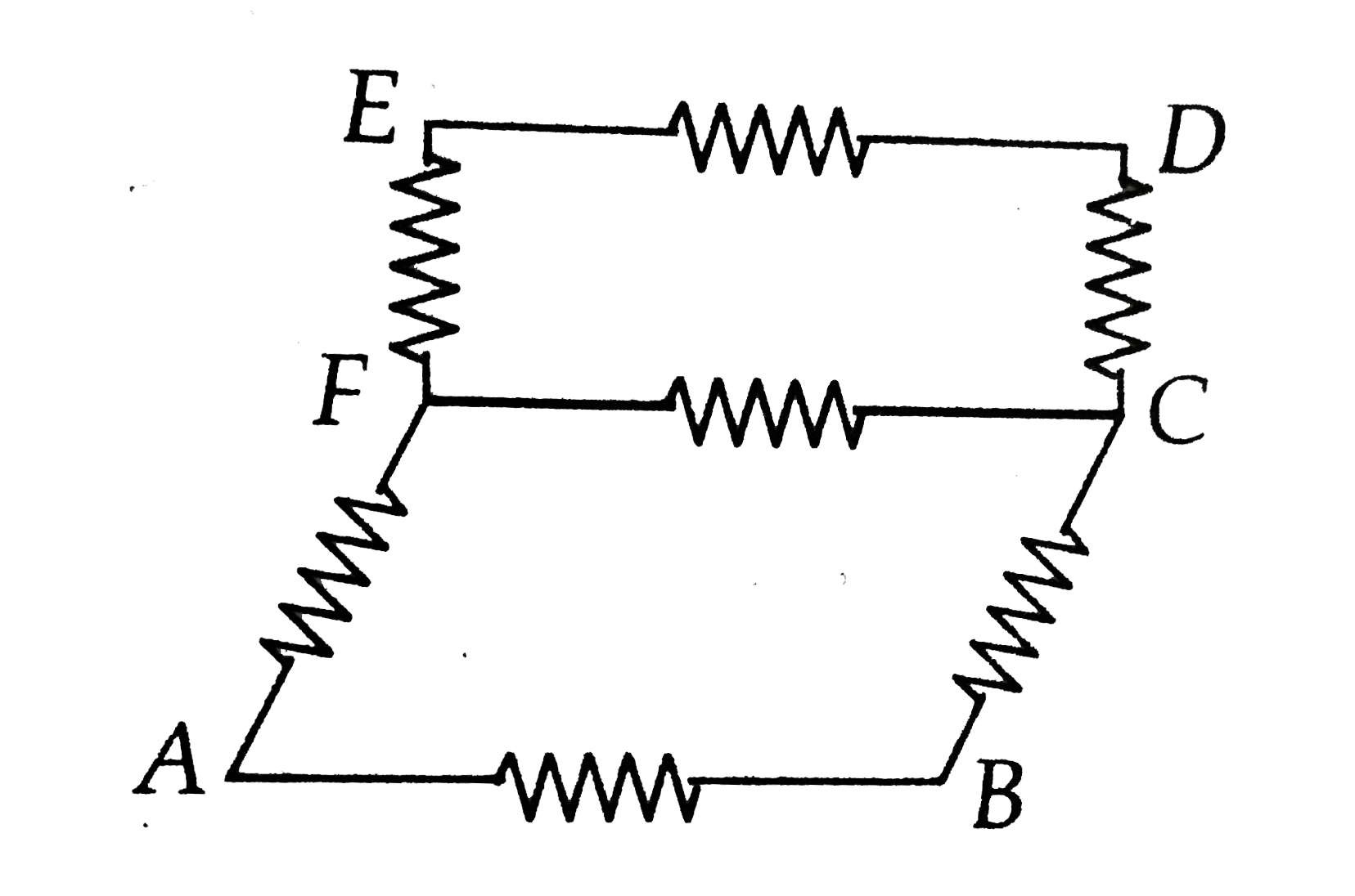
View SolutionIf the potential difference between A and D is V, what will be potential difference between F and C. each of the resistance is R.
View SolutionAn ammeter and a voltmeter are joined in sereis to a cell. Their readings are A and V respectively. If a resistance is now joinding parallel with the voltmeter. Then
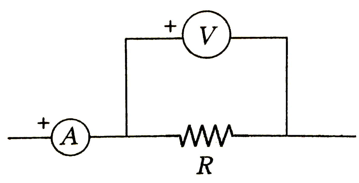
View SolutionAn ammeter A, a voltmeter V and a resistance R are connected as shown in the figure. If the voltmeter reading is 1.6V and the ammeter reading is 0.4A, then R is
View Solution
