Two resistors R1andR2 can slide without friction along two parallel metal guides dierected at an angle α to the horizontal and separated by a distance b . The guides are not connected at the bottom as shown. The entire system is placed in an upward magnetic field which decreases with time as dBdt=β, x = 0 and x - axis is along the guide as shown in the figure. The resistors are made to slide with a constant velocity v downwards .
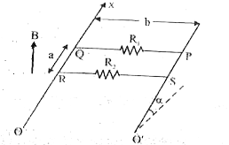
The emf induced due to decreases of B with time only ( and the direction of current in loop ) respectively (ACW → anticlockwise, CW → clockwise )
ab α (ACW)
a2bα (CW)
ab α( CW)
a2bα(ACW)
The correct Answer is:A
ϕ = ab B
e = - dϕdt=ab(−dBdt)=abα anticlockwise as seen from above.
∴ (A)
Topper's Solved these Questions
- ELECTROMAGNETIC INDUCTIONBOOK - FIITJEECHAPTER - ELECTROMAGNETIC INDUCTIONEXERCISE - Comprehension Based Type Comprehension -III
2 Videos
- ELECTROMAGNETIC INDUCTIONBOOK - FIITJEECHAPTER - ELECTROMAGNETIC INDUCTIONEXERCISE - Assertion Reasoning Type
1 Videos
- ELECTROMAGNETIC INDUCTIONBOOK - FIITJEECHAPTER - ELECTROMAGNETIC INDUCTIONEXERCISE - Comprehension Based Type Comprehension -I
3 Videos
- ELASTICITY AND WAVES BOOK - FIITJEECHAPTER - ELASTICITY AND WAVES EXERCISE - Assignment Problems (Objective) Level-II
15 Videos
- ELECTROMAGNETIC INDUCTION AND AC CURRENTBOOK - FIITJEECHAPTER - ELECTROMAGNETIC INDUCTION AND AC CURRENTEXERCISE - Example
15 Videos
Similar Questions
A conducting bar is slid at a constant velocity v along two conducting rods. The rods ar seprated by a distance l and connected across a resistor R. The entire apparatus is placed in an external magnetic field B directed into the page
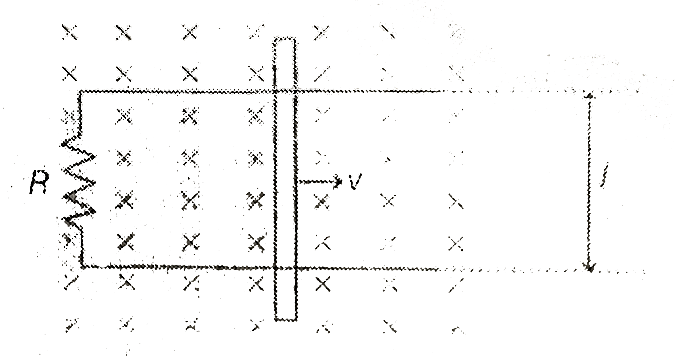
The induced current in the above circuit is:
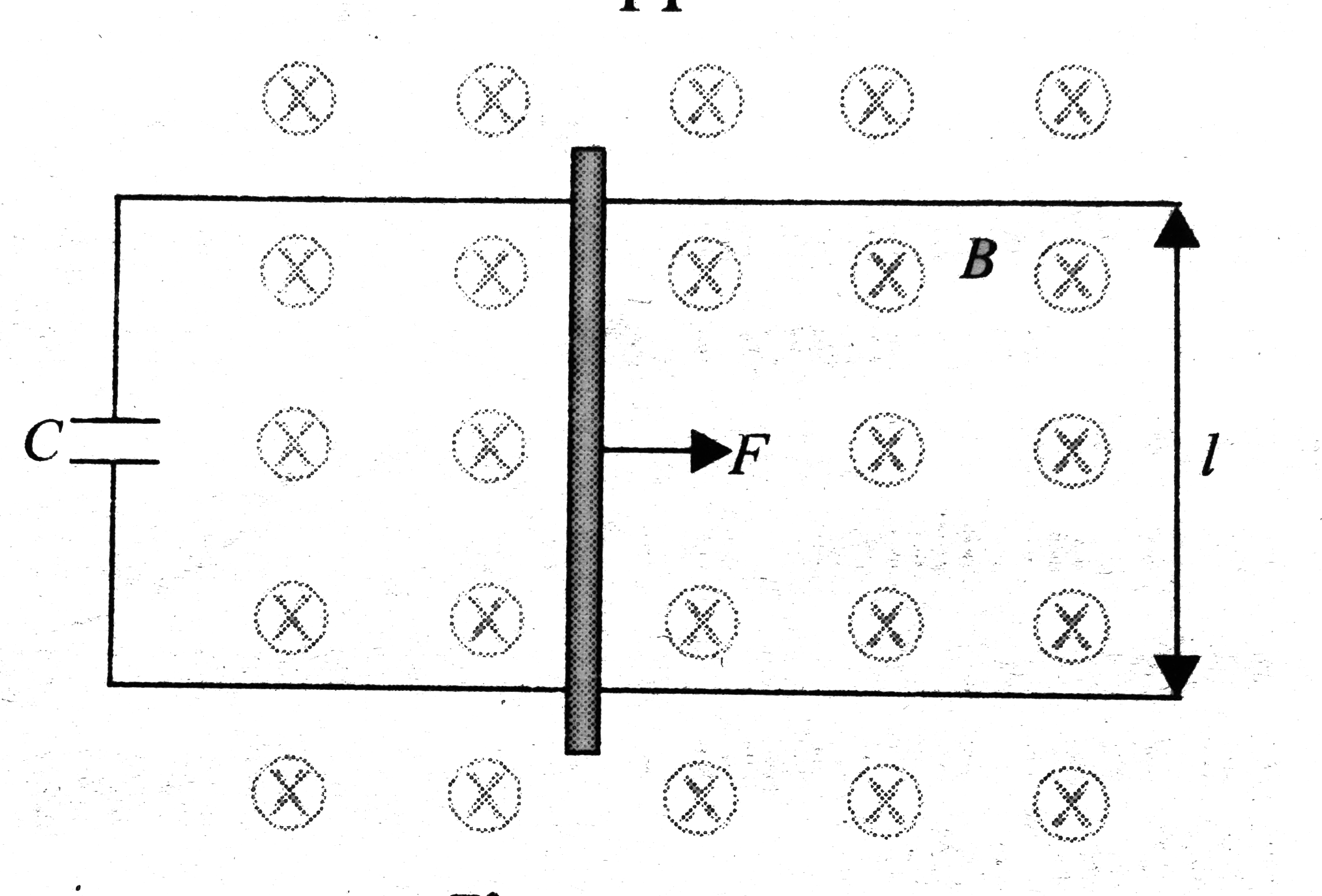
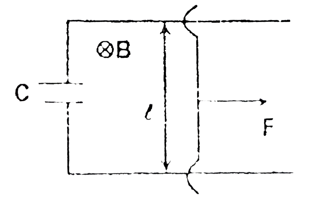
View SolutionA conducting wire of length l and mass m can slide without friction on two parallel rails and is connected to capacitance C. The whole system lies in amagnetic field B and a constant force F is applied to the rod . Then
View Solution
Knowledge Check
Two resistors R1andR2 can slide without friction along two parallel metal guides dierected at an angle α to the horizontal and separated by a distance b . The guides are not connected at the bottom as shown. The entire system is placed in an upward magnetic field which decreases with time as dBdx=β, x = 0 and x - axis is along the guide as shown in the figure. The resistors are made to slide with a constant velocity v downwards .
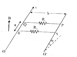
The emf induced due to decrease in B due to change in position onlyAβ abv(CW)Bβabv (ACW)Cβ2 av (CW)Dβ2 av (ACW)A conducting bar is slid at a constant velocity v along two conducting rods. The rods ar seprated by a distance l and connected across a resistor R. The entire apparatus is placed in an external magnetic field B directed into the page

The induced current in the above circuit is:AsinusoidalBclockwiseCcounterclockwiseDthere is not enough information to determine the direction and nature of the currentA conducting wire of length l and mass m can slide without friction on two parallel rails and is connected to capacitance C. The whole system lies in amagnetic field B and a constant force F is applied to the rod . Then
 A(a) the rod moves with constant velocity.B(b) the rod moves with an acceleration of (F)/(m+B2l2C).C(c ) there is constant charge on the capacitor.D(d) charge on the capacitor increases with time.
A conducting wire of length l and mass m can slide without friction on two parallel rails and is connected to capacitance C. Whole system lies in a magnetic field B and a constant force F is applied to the rod. Then
View SolutionThree charges are placed along x-axis at x = - a x = 0 and x = a as shown in the figure. The potential energy of the system is

View SolutionA conducting wire of length l and mass m can slide without friction on two parallel rails and is connected to capacitance C. The whole system lies in a magnetic field B and a constant force F is applied to the rod. Then
View SolutionA conducting wire of length l and mass m can slide without friction on two parallel rails and is connected to capacitance C. Whole system lies in a magnetic field B and a constant force F is applied to the rod. Then

View SolutionThree charges are placed along x-axis at x = - a x = 0 and x = a as shown in the figure. The potential energy of the system is

View Solution
