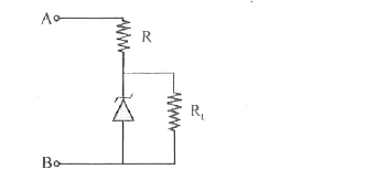
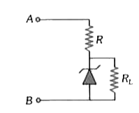
If the voltage between the terminals A and B is 17 V and Zener breakdown voltage is 9 V , then the potential across R is
 Solution in Tamil
A) 6 V
B) 8 V
C) 9 V
D) 17 V
The correct Answer is:B
Step by step video, text & image solution for If the voltage between the terminals A and B is 17 V and Zener breakdown voltage is 9 V , then the potential across R is by Physics experts to help you in doubts & scoring excellent marks in Class 12 exams.
Topper's Solved these Questions
- BOOK - NEW JOYTHI PUBLICATIONCHAPTER - SEMICONDUCTOR ELECTRONICS : MATERIALS , DEVICES AND SIMPLE CIRCUITS EXERCISE - PREVIOUS YEAR QUESTIONS3videos
SEMICONDUCTOR ELECTRONICS : MATERIALS , DEVICES AND SIMPLE CIRCUITS
- BOOK - NEW JOYTHI PUBLICATIONCHAPTER - RAY OPTICS AND OPTICAL INSTRUMENTS EXERCISE - COMPETITIVE EXAM CORNER26videos
RAY OPTICS AND OPTICAL INSTRUMENTS
- BOOK - NEW JOYTHI PUBLICATIONCHAPTER - WAVE OPTICSEXERCISE - COMPETITIVE EXAM CORNER17videos
WAVE OPTICS
Similar Questions
We are familiar with the semi conductors Silicon and Germanium .
a. With a necessary schematic diagram , briefly explain the characteristics of an intrinsic semiconductor.
b. Draw the energy bands of a n-type semiconductor.
c The following figure represents a
d . Draw a typically illuminated P-n junctions solar cell.
e. LED convert............ energy to light.02:44View SolutionA 100 W bulb produces an electric field of 2.9 V/m at a point 3m away. If the bulb is replaced by 400 W bulb without disturbing other conditions. Then the electric field produced at the same point is
01:21View SolutionYoung's experiment is performed with light of wavelength 6000Å where in 16 frignes occupy a certain region on the screen. If 24 fringes occupy the same region with another light of wavelength λ then λ is
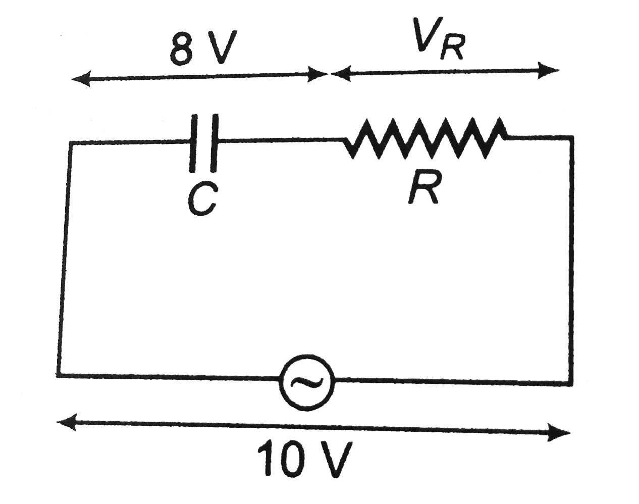
01:10View SolutionIn a series C−R circuit shown in figureure, the applied voltage is 10V and the voltage across capacitor is found to8V. The voltage across R, and the phase difference between current and the applied voltage will respectively be
 .05:05View Solution
If the voltage between the terminals A and B is 17V and zener breakdown voltage is 9V , then the potential across R is
04:03View SolutionIn an L-C-R series circuit, the potential difference between the terminals of the inductance is 60 V, between the terminals of the capacitor is 30 V and that across the resistance is 40 V. Then, the supply voltage will be equal to
03:10View SolutionWhen breakdown voltage of a Zener diode is around 6 V, then the value of this voltage does not depend upon temperature -Explain.
View SolutionIn the figure there is a DC voltage regulator circuit, with a Zener breakdown voltage = 6V.If the unregulated input voltage varies between 10V to 16V,then what is the maximum Zener current?
01:21View SolutionIn a LCR series circuit, the potential difference between the terminals of the inductance is 60 V, between the terminals of the capacitor is 30 V nd that across the resistance is 40 V. Then, then supply voltage will be equal to
02:01View SolutionAssertion (A) : Zener diode works on the principle of breakdown voltage.
Reason (R) : Current increases suddenly after breakdown voltage.02:06View Solutionयदि सिरों A व B के मध्य वोल्टेज 17 V तथा जेनर भंजन वोल्टेज 9Vहो, तब R के सिरों पर विभवान्तर होगा
 02:43View Solution
If the voltage between the terminals A and B is 17 V and Zener brekdown voltage is 9 V, then the potential across R is
 02:32View Solution
In a series C−R circuit shown in figureure, the applied voltage is 10V and the voltage across capacitor is found to8V. The voltage across R, and the phase difference between current and the applied voltage will respectively be
 .02:07View Solution
In an L-C-R series circuit, the potential difference between the terminals of the inductance is 60 V, between the terminals of the capacitor is 30 V and that across the resistance is 40 V. Then, the supply voltage will be equal to
03:30View SolutionIn a series C-R circuit shown in figureure, the applied voltage is 10 V and the voltage across capacitor is found to 8 V . The voltage across R , and the phase difference between current and the applied voltage will respectively be .
02:44View Solution

