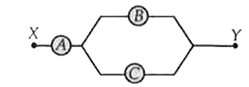
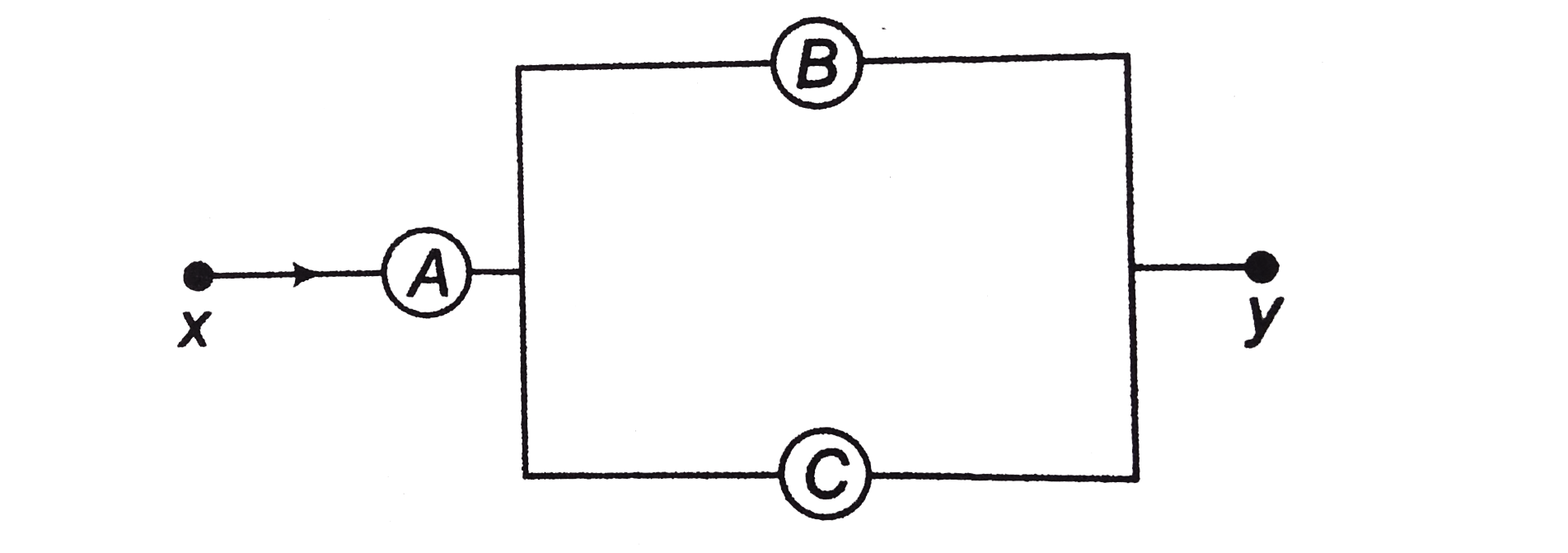
The voltmeters A,B, and C having resistance R, 1.5R and 3R respectively are used in a circuit as shown, When a P.D. is applied between X and Y, the reading of the voltmeters are V1,V2 and V3 respectively Then
 Solution in Kannada
V1=V2=V3
V1<V2=V3
V1>V2>V3
V1>V2=V3
The correct Answer is:A
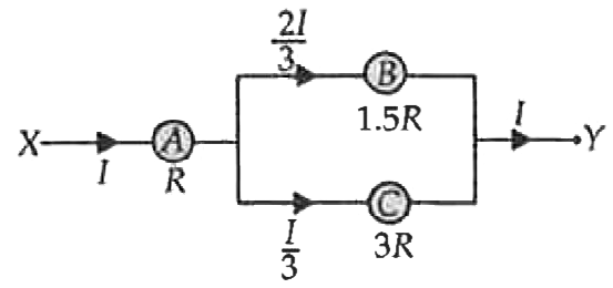
V1=IR
V2=2I3×1.5R=IR,V3=I3×3R=IR
∴V1=V2=V3
Topper's Solved these Questions
Similar Questions
In ruby laser, the stimulated emission is due to transition from
03:03View SolutionWhich of the following graphs correctly represents the variation of heat energy (U) produced in a metallic conductor in a given time as a function of potential difference (V) across the conductor ?
02:47View SolutionConsider the circuit shown in the figure, the cell is ideal. The readings of the ideal voltmeters V_(1) and V_(2) in volts are respectively.
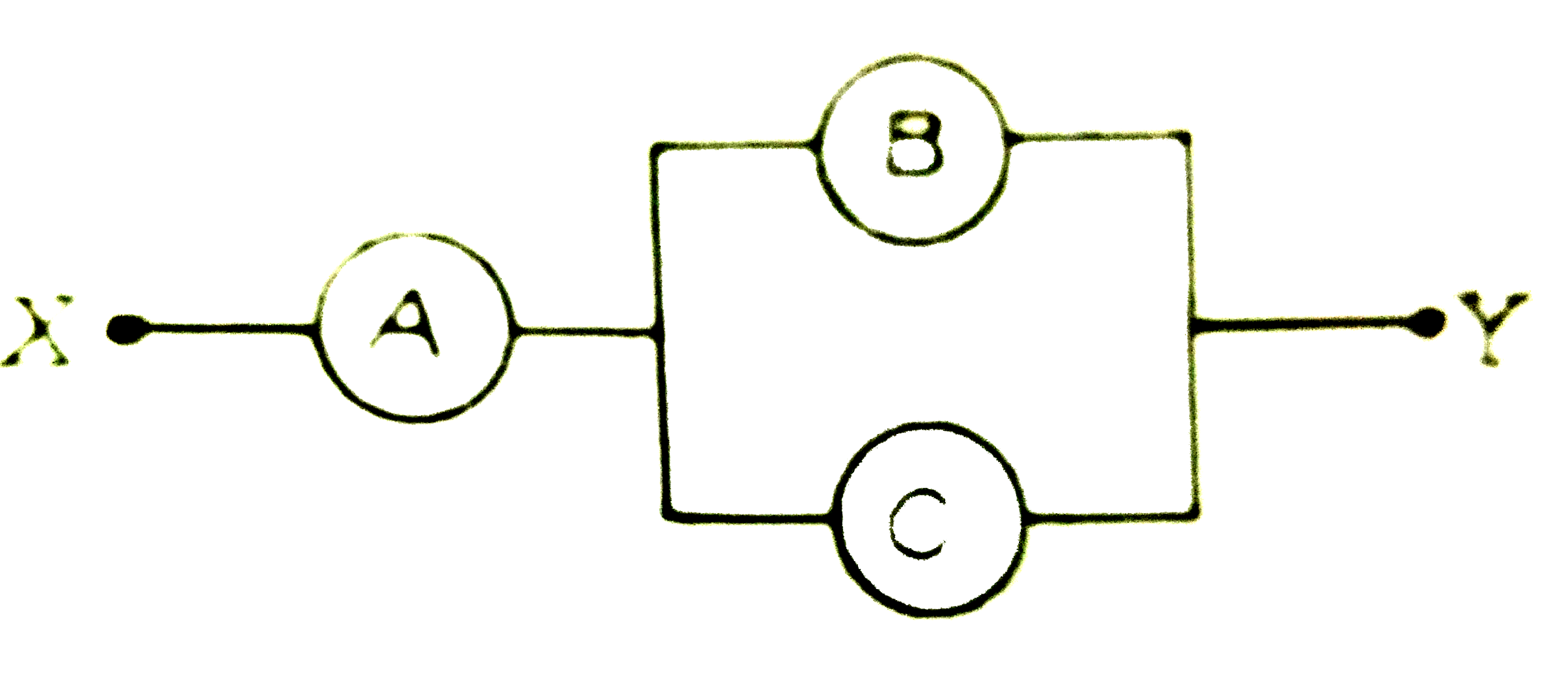
02:41View Solutionआरेख में दिखाये गये वोल्टमीटरों A , B तथा C के प्रतिरोध क्रमशः R, 1.5 R तथा 3 R हैं । जब X तथा Y के बीच कुछ विभवान्तर लगाया जाता है तो इनके पाठ क्रमशः VA,VB तथा VC हैं तब :
 02:10View Solution
यदि किसी L-C-R परिपथ में VL,VR,VC तथा V0 क्रमशः प्रेरकत्व, प्रतिरोध, संधारित्र तथा स्रोत में लगे AC वोल्टमीटर के पाठ्यांक हों, तो :
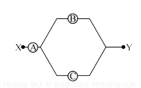
06:15View SolutionThree voltmeters A, B and C having resistances R, 1.5 R and 3 R respectively are used in a circuit as shown. When a potential difference is applied between X and Y, the readings of the voltmeters are V1,V2andV3respectively. Then :
 03:33View Solution
A, B and C arc voltmeters of resistance R, 1.5R and 3R respectively as shown in the figure. When some potential difference is applied between X and Y, the voltmeter readings are VA,VBandVC repsectively. Then :
03:58View SolutionA,B and C are voltmeters of resistance R, 1.5 R and 3R respectively as shown in the fig. When some potential difference is applied between X and Y, the voltmeter reading are VA,VBandVC respectively.
 View Solution
A, B and C are voltmeters of resistance R, 1.5R and 3R respectively as shown in the figure. When some potential difference is aaplied between X and Y, the voltmeter readings are VA,VB and VC respectively, then
 02:27View Solution
A, B and C are voltmeters of resistance R, 1.5R and 3R respectively as in fig. when some P.D. is applied between x and y, the voltmeter readings are V_A, V_B and V_C respectively, then:
01:48View SolutionA, B and C are voltmeters of resistances R, 1.5R and 3R respectively. When some potential difference is applied between x and y the voltmeter readings are V_A, V _B and V_C, then
02:23View SolutionThree voltmeters A,B and C having resistances R, 1.5 R and 3R respectively are used in a circuit as shown
 . When a P.D. is applied between X and Y, the reading of the voltmeters are V1,V2 and V3 respectively. Then....02:29View Solution
A,B and C are voltmeters of resistances R,1.5R and 3R respectively. When some potential difference is applied between x and y the voltmeter readings are VA,VBandVC, then
 02:18View Solution
Consider the circuit shown in the figure, the cell is ideal. The readings of the ideal voltmeters V_(1) and V_(2) in volts are respectively.
02:10View SolutionThree voltmeters A, B and C having resistances R, 1.5 R and 3 R respectively are used in a circuit as shown. When a potential difference is applied between X and Y, the readings of the voltmeters are V_1, V_2 and V_3 respectively. Then :
04:38View Solution

