Consider the circuit shown in the figure, the cell is ideal. The readings of the ideal voltmeters V1 and V2 in volts are respectively.

2,0
0,2
0,0
2,2
The correct Answer is:B
Since current through cell is negligible the potential difference across 5 ohm resistor tends to zero, and the potential difference across V2 will be 5V.
Topper's Solved these Questions
- BOOK - RESONANCE ENGLISHCHAPTER - DAILY PRACTICE PROBLEMEXERCISE - DPP No.489videos
DAILY PRACTICE PROBLEM
- BOOK - RESONANCE ENGLISHCHAPTER - DAILY PRACTICE PROBLEMEXERCISE - DPP No.4920videos
DAILY PRACTICE PROBLEM
- BOOK - RESONANCE ENGLISHCHAPTER - DAILY PRACTICE PROBLEMEXERCISE - DPP No.4611videos
DAILY PRACTICE PROBLEM
- BOOK - RESONANCE ENGLISHCHAPTER - CURRENT ELECTRICITYEXERCISE - High Level Problems (HIP)19videos
CURRENT ELECTRICITY
- BOOK - RESONANCE ENGLISHCHAPTER - ELECTRO MAGNETIC WAVESEXERCISE - Exercise 327videos
ELECTRO MAGNETIC WAVES
Similar Questions
Knowledge Check
- Question 1 - Select One
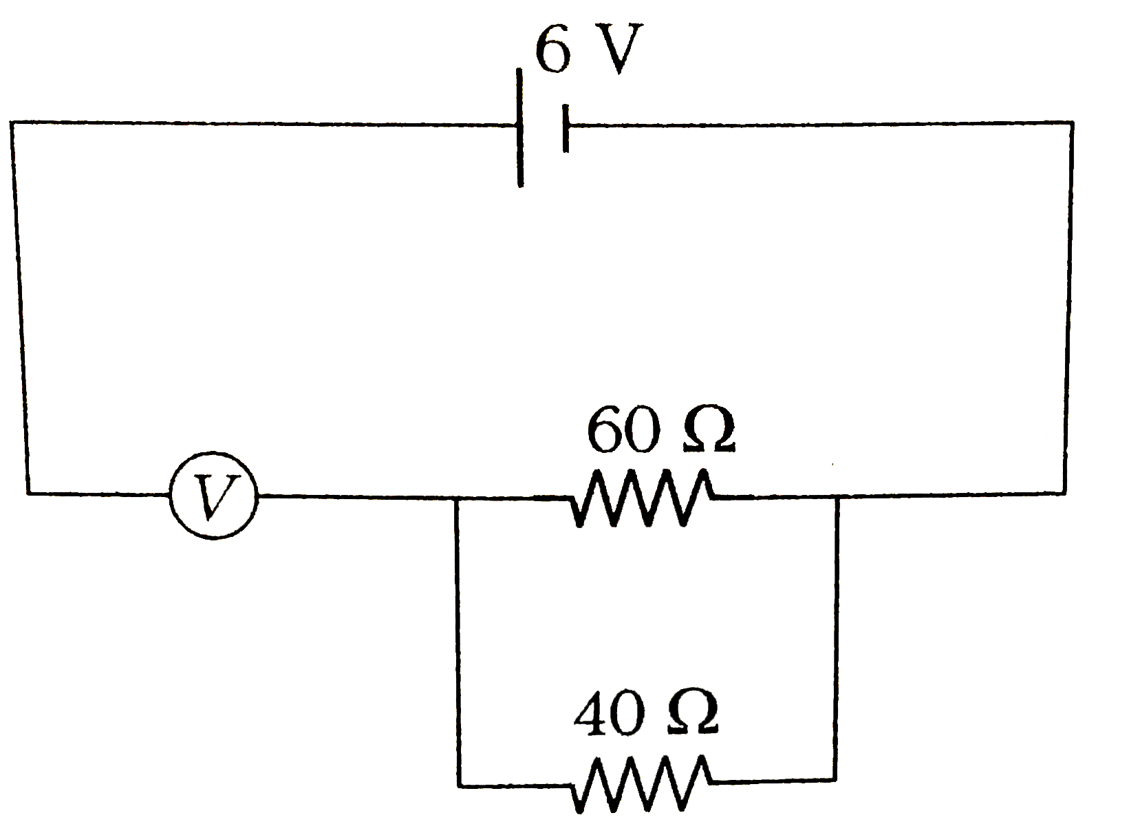
In the circuit shown in figure, what will be the reading of the voltmeter ?
 A300 VB900 VC200 VD400 V
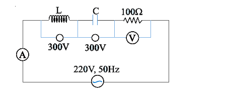
In the circuit shown in figure, what will be the readings of voltmeter and ammeter?
 View Solution
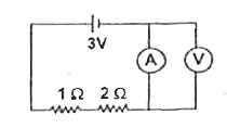
Is correct. In the circuit shown in the figure, the voltmeter reading would be.
 View Solution
In the given circuit, the voltmeter and the electric cell are ideal. Find the reading of the voltmetre
 View Solution
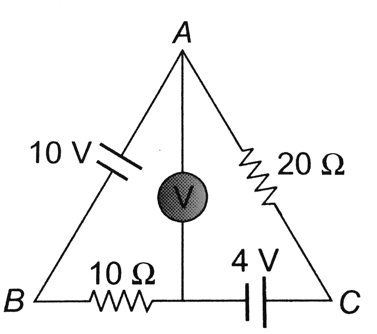
The reading of the ideal voltmeter in the adjoining diagram will be
 View Solution
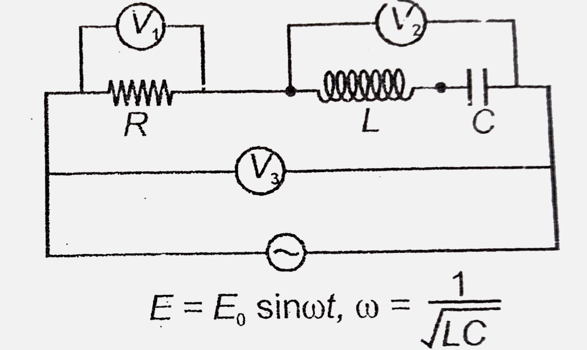
In the circuit shown, the readings of voltmeters V1,V2andV3 are given by
 View Solution
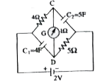
In the circuit shown in Fig., the cell is ideal with e.m.f = 2V. The resistance of the coil of the galvanometer G is 1Ω. Then
 View Solution
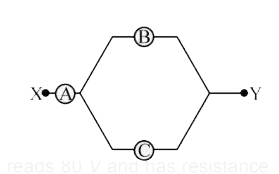
Three voltmeters A, B and C having resistances R, 1.5 R and 3 R respectively are used in a circuit as shown. When a potential difference is applied between X and Y, the readings of the voltmeters are V1,V2andV3respectively. Then :
 View Solution


