The magnetic field B through the rectangle of Fig. 32-6 is shown at a different instant in part 1 of the figure here, B is directed in the xz plane, parallel to the z axis, and its magnitude is increasing. (a) Complete part 1 by drawing the induced electric fields, indicating both directions and relative magnitudes (as in Fig. 32-6). (b) For the same instant, complete part 2 of the figure by drawing the e lectric field of the electromagnetic wave. Also draw the induced magnetic fields, indicating both directions and relative magnitudes (as in Fig. 32-7).
(a) Use Eq. 32 -5 . On the right side of rectangle →E is in the negative y direction on the left side →E+d→E is greater and in the same direction (b) →E is downward . On the right side →B is in negative z -direction on the left side →B+d→B is greater and in the same direction .
Topper's Solved these Questions
- ELECTROMAGNETIC WAVES BOOK - RESNICK AND HALLIDAYCHAPTER - ELECTROMAGNETIC WAVES EXERCISE - PROBLEMS
29 Videos
- ELECTROMAGNETIC WAVES BOOK - RESNICK AND HALLIDAYCHAPTER - ELECTROMAGNETIC WAVES EXERCISE - PRACTICE QUESTIONS (Single Correct Choice Type )
62 Videos
- ELECTROMAGNETIC WAVES BOOK - RESNICK AND HALLIDAYCHAPTER - ELECTROMAGNETIC WAVES EXERCISE - PRACTICE QUESTIONS (Integer Type)
3 Videos
- ELECTROMAGNETIC OSCILLATIONS AND ALTERNATING CURRENT BOOK - RESNICK AND HALLIDAYCHAPTER - ELECTROMAGNETIC OSCILLATIONS AND ALTERNATING CURRENT EXERCISE - Practice Questions (Integer)
7 Videos
- FLUIDSBOOK - RESNICK AND HALLIDAYCHAPTER - FLUIDSEXERCISE - PRACTICE QUESTIONS (Integer Type )
5 Videos
Similar Questions
Fleming's Right hand rule gives
(A) magnitude of induced current
(B) magnitude of magnetic field
(C) direction of induced current
(D) both direction and magnitude of induced current.
View SolutionFleming's Right hand rule gives
(A) magnitude of induced current
(B) magnitude of magnetic field
(C) direction of induced current
(D) both direction and magnitude of induced current.
View Solution
Knowledge Check
The magnet in fig. rotates as shown on a pivot through its center. At the instant shown, the directions of the induced currents are:
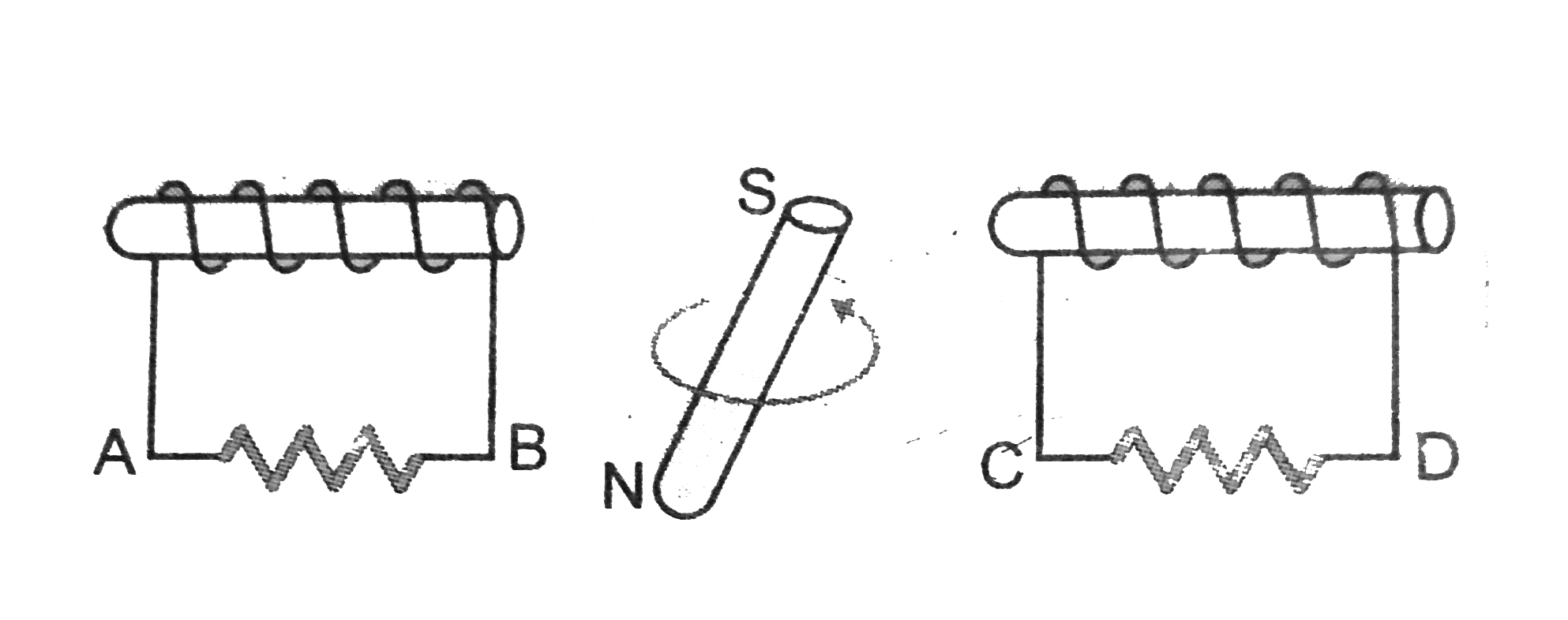 AA to B and C to DBB to A and C to DCA to B and D to CDB to A and D to C
A plane polarized electromagnetic wave of frequency 6×10⁸Hz is propagating through a region of space. Electric field is along positive z-direction and magnetic field is along positive y-direction at some instant. The peak value of electric field is 3 milli-volt/m.
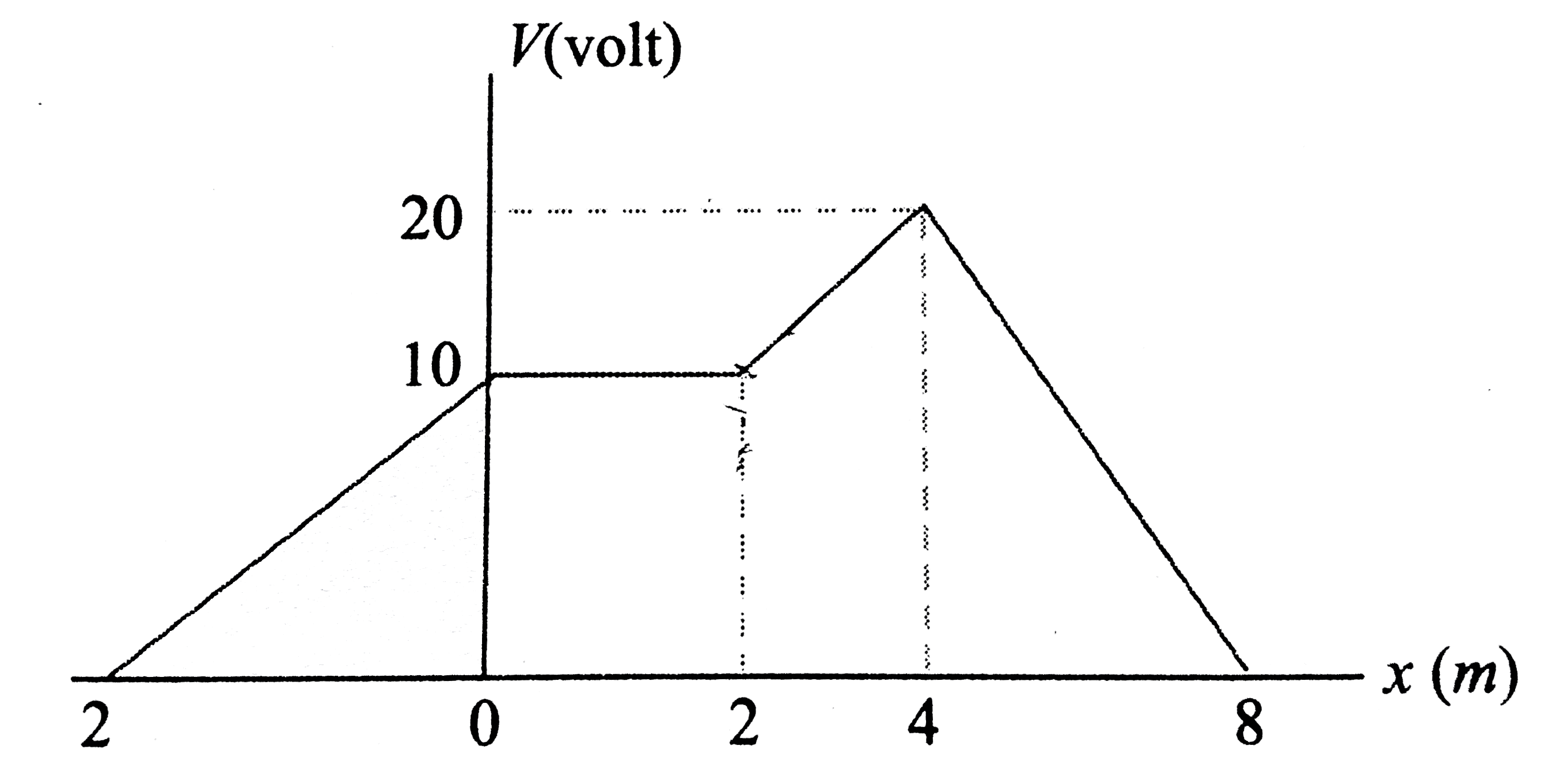
The direction of propagation of wave isAB=(10−8sin2π[2x−(6×10⁻⁸)t]BB=(10−11sin2π[2x−(6×10⁻⁸)t]CB=(10−11sin2π[2x−(6×10⁻⁸)t]DB=(10−11sin2π[2x−(6×10⁻⁸)t]The electrical potential function for an electrical field directed parallel to the x - axis is shown in (Fig. 3.152).
 .
.
The magnitude of the electric field in the x - direction in the interval 4≤x≤8 isA2.5NC−1B5NC−1C−2.5NC−1D−5NC−1
Establish the relation between electric field and electric potential at a point. Draw the equipotential surface for an electric field pointing in +Z direction with its magnitude increasing at constant rate along -Z direction
View SolutionThe potential difference (VA−VB) between points A and B in a part of an electrical circuit shown in the figure at the instant shown is
_PHY_E05_273_Q01.png)
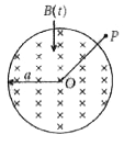
View SolutionA uniform but time varying magnetic field B(t) exist in a circular region of radius a and is directed into the plane of the paper as shown. The magnitude of the induced electric field at point P at a distance r form the centre of the circular region.
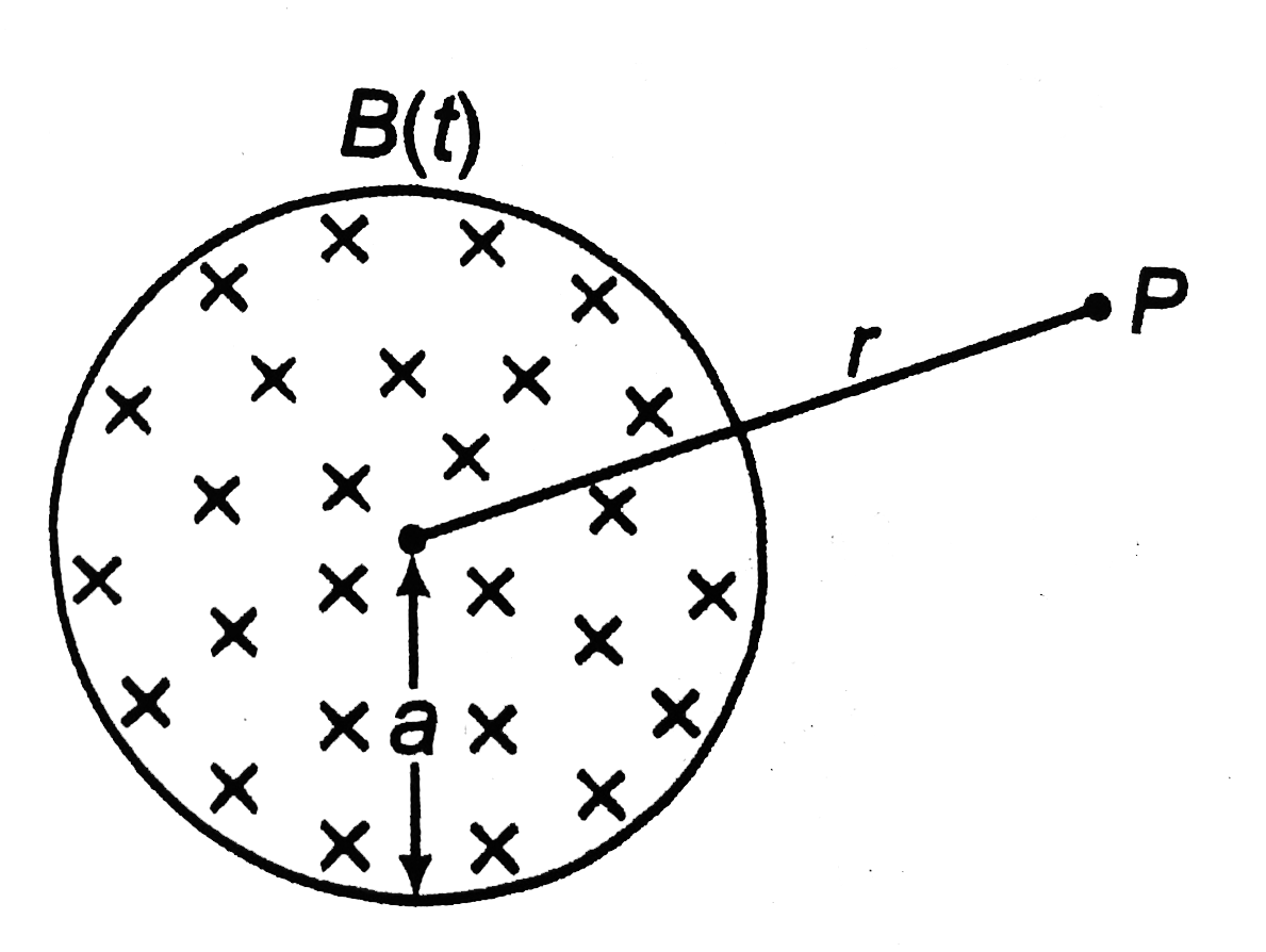
View SolutionA uniform but time-varying magnetic field B(t) exists in a circular region of radius a and is directed into the plane of the paper, as shown in the figure. The magnitude of the induced electric field at point P at a distance r from the centre of the circular region
View Solution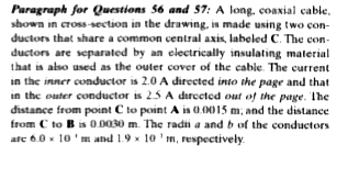
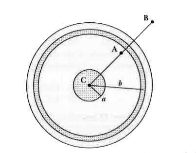 What is the magnitude and direction of the magnetic field at point B ?
View Solution
