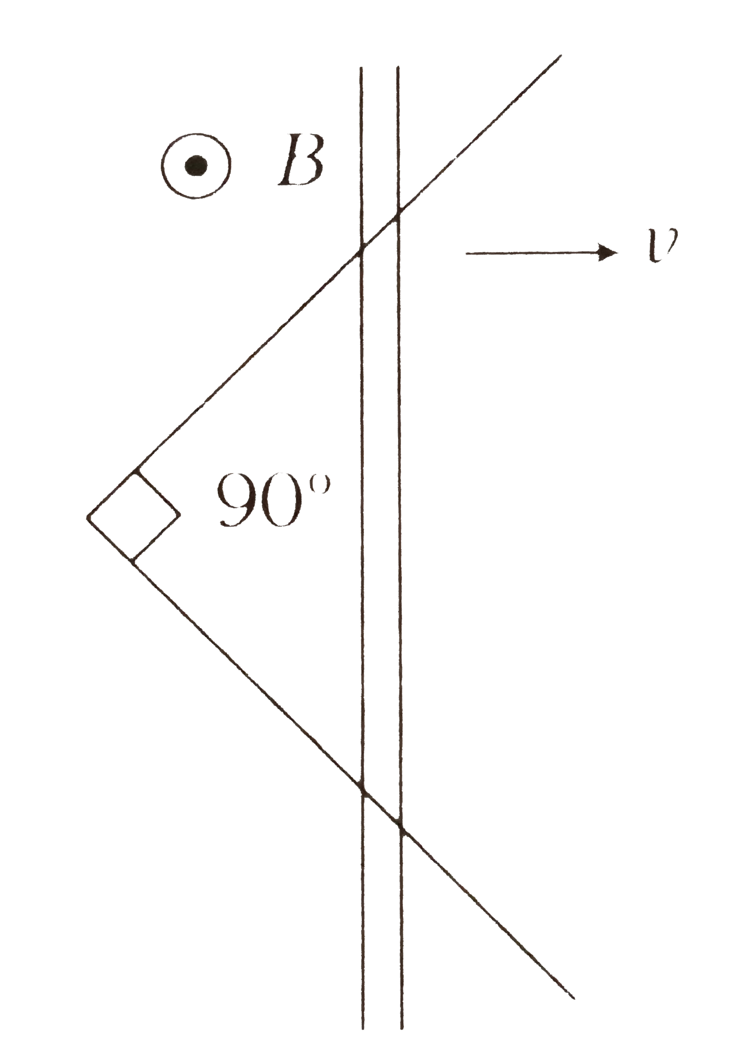
Two straight conducting rails form a right angle where their ends are joined. A conducting bar in contact with the rails starts at the vertex at time t = 0 and moves with constant velocity v along them as shown in Fig. A magnetic field →B is directed into the page. the induced emf in the circuit at any time t is proportional to

(a) 85.2 Wb, (b) 56.8 V, (c) 1
Topper's Solved these Questions
- BOOK - RESNICK AND HALLIDAYCHAPTER - ELECTROMAGNETIC INDUCTIONEXERCISE - PRACTICE QUESTIONS (Single Correct Choice Type)45videos
ELECTROMAGNETIC INDUCTION
- BOOK - RESNICK AND HALLIDAYCHAPTER - ELECTROMAGNETIC INDUCTIONEXERCISE - PRACTICE QUESTIONS (More than One Correct Choice Type)13videos
ELECTROMAGNETIC INDUCTION
- BOOK - RESNICK AND HALLIDAYCHAPTER - ELECTROMAGNETIC INDUCTIONEXERCISE - CHECKPOINTS9videos
ELECTROMAGNETIC INDUCTION
- BOOK - RESNICK AND HALLIDAYCHAPTER - ELECTRIC POTENTIALEXERCISE - (PRACTICE QUESTIONS) Integer Type1videos
ELECTRIC POTENTIAL
- BOOK - RESNICK AND HALLIDAYCHAPTER - ELECTROMAGNETIC OSCILLATIONS AND ALTERNATING CURRENT EXERCISE - Practice Questions (Integer)7videos
ELECTROMAGNETIC OSCILLATIONS AND ALTERNATING CURRENT
Similar Questions
Two straight conducting rails form a right angle where their ands are joined. A conducting bar contanct with the rails starts at vertex at the time t=0 & moves symmetrically with a constant velocity of 5.2m/s to the right as shown in figure. A 0.35T magnetic field point out of the page. Calculate:
(i) The flux through the tringle by the rails & ber at t=3.0s.
(ii) The emf around the tringle at that time.
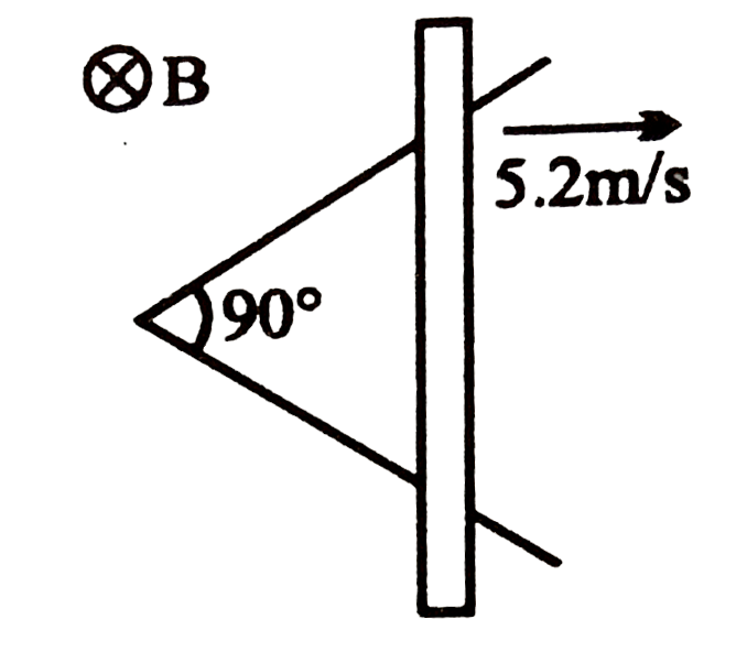
In what manner does the emf around the tringle vary with time.View SolutionTwo straight conducting rails from a right angle where their end are joined. A conducting bar polaced over the rails starts at vertex at the time t=0 and moves with a constant velocity v to the right as shown in the figure. Calculate
(a) the flux through the triangle (isosceles) by the rails and bar at t=t0
the emf around the triangle at that time
(c) in what manner does the emf around the triangle vary with time View Solution
Knowledge Check
- Question 1 - Select One
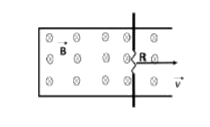
A conducting rod, with a resistor of resistance R. is pulled with constant speed v on a smooth conducting rail as shown in figure. A constant magnetic field →B is directed into the page. If the speed of the bar is doubled, by what factor does the rate of heat dissipation across the resistance R change?
 A0B√2C2D4
 - Question 2 - Select One
A conducting bar is slid at a constant velocity v along two conducting rods. The rods ar seprated by a distance l and connected across a resistor R. The entire apparatus is placed in an external magnetic field B directed into the page
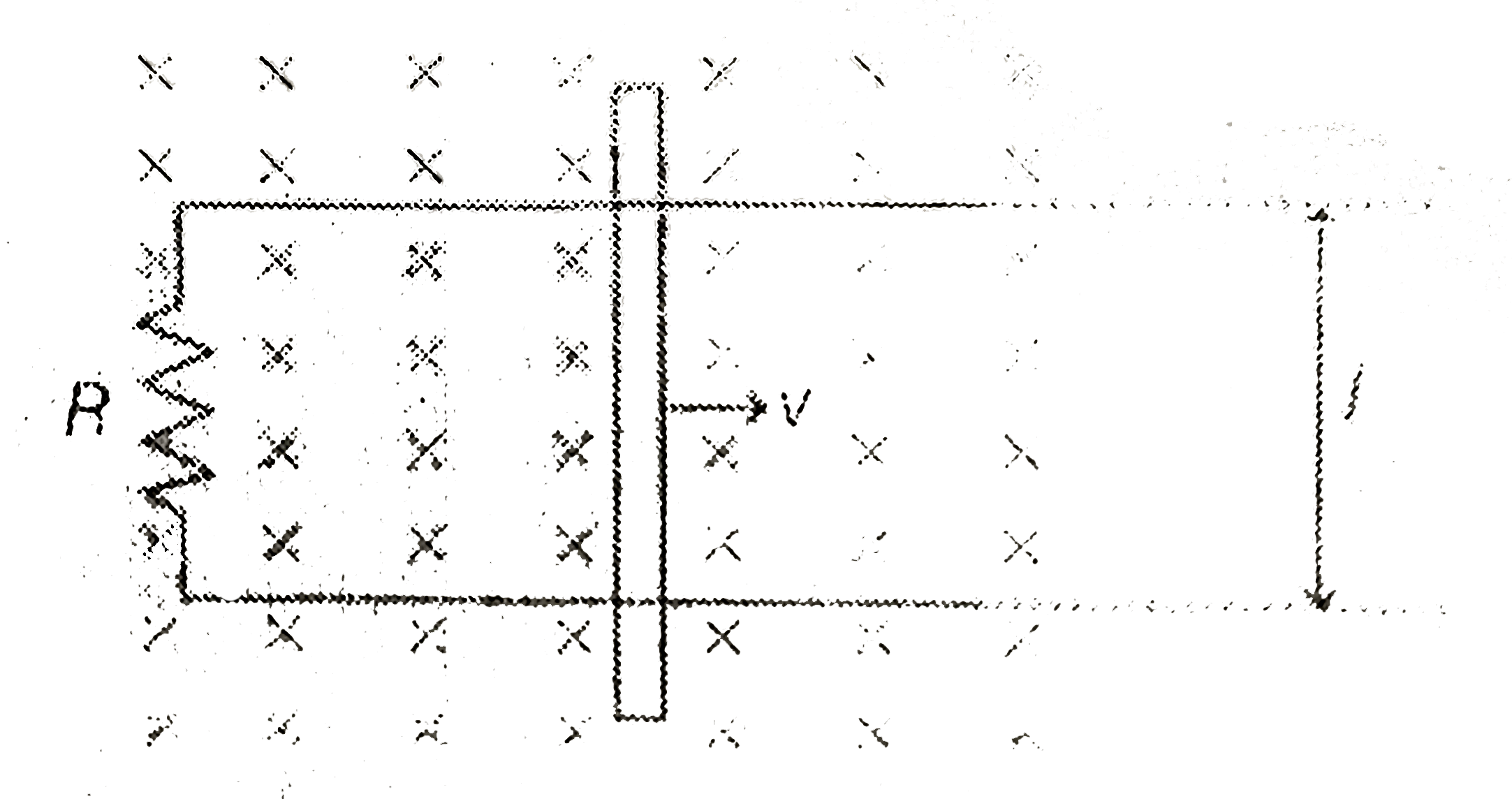
The induced current in the above circuit is:AsinusoidalBclockwiseCcounterclockwiseDthere is not enough information to determine the direction and nature of the current - Question 3 - Select One
A rod of length 10cm made up of conducting and non-conducting material (shaded part is non-conducting). The rod is rotated with constant angular velocity 10rad/s about point O, in constant magnetic field of 2T as shown in the figure. The induced emf between the point A and B of rod will be:
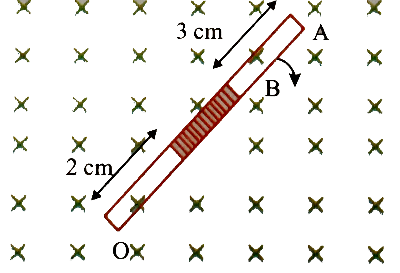 A0.029VB0.1VC0.051D0.064V
A conducting rod, with a resistor of resistance R. is pulled with constant speed v on a smooth conducting rail as shown in figure. A constant magnetic field →B is directed into the page. If the speed of the bar is doubled, by what factor does the rate of heat dissipation across the resistance R change?
 View Solution
The two conducting rails are placed perpendicular to each other, such that their ends are joined as shown in figure. A conducting bar is now placed over the rails and start moving with constant velocity v starting from the vertex at time t = 0.
(i) The flux through the triangle (isosceles) by the rails and bar at t=t0.
(ii) The emf around the triangle at that time.
(iii) In what manner does the emf around the triangle vary with time.
 View Solution
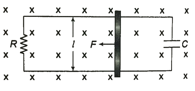
Two parallel long smooth conducting rails separated by a distance l are connected by a movable conducting connector of mass m. Terminals of the rails are connected by the resistor R and the capacitor C as shown in figure. A uniform magnetic field B perpendicular to the plane of the rail is switched on. The connector is dragged by a constant force F. Find the speed of the connector as a function of time if the force F is applied at t=0. Also find the terminal velocity of the connector.
 View Solution
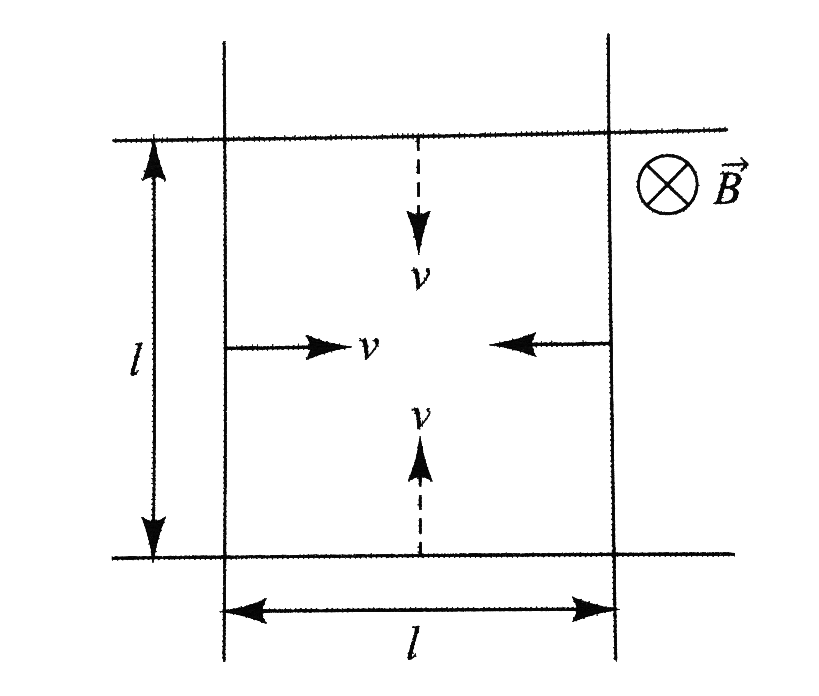
in fig. The four rods have λ resistance per unit length. The arrengement is kept in a magnetic field of constant magnitude B and directed perpendicular to the plane of the figure and directing in ward. Initially, the sides as shown form a square. Now each wire starts moving with constant velocity v toward the opposite wire.
Find as a function of time:
(a) induced emf in the circuit.
(b) induced current in the circuit with direction.
( c ) force required on each wire to keep its velocity consatnt.
(d) total power required to maintain constant velocity.
(e) thermal power developed in the circuit.
 View Solution
The conducting rod shown in Fig. 30-37 has length Land is being pulled along horizontal, frictionless conducting rails at a constant velocity →v. The rails are connected at one end with a metal strip. A uniform magnetic field →B, directed out of the page, fills the region in which the rod moves. Assume that L = 10 cm, v = 5.0 m/s, and B = 1.2 T. What are the (a) magnitude and (b) direction (up or down the page) of the emf induced in the rod? What are the (c) size and (d) direction of the current in the conducting loop? Assume that the resistance of the rod is 0.40 Ω and that the resistance of the rails and metal strip is negligibly small. (e) At what rate is thermal energy being generated in the rod? (f) What external force on the rod is needed to maintain →v? (g) At what rate does this force do work on the rod?
View Solution

