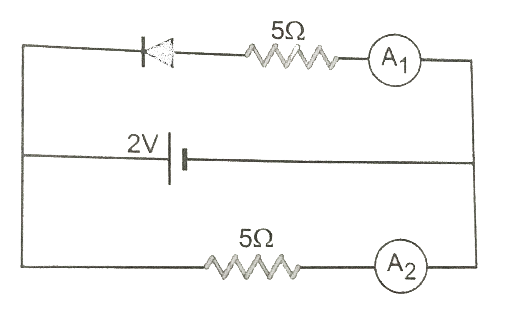
What are the reading of the ammeters shown in figure (Assuming diodes and ammeters are ideal)

A
0,0.2 A
B
0.2A, 0
C
0.2 A, 0.2A
D
0.1 A, 02 A
Text Solution
The correct Answer is:A
The diode is in reverse bias, so it will conduct. Therefore
|
Topper's Solved these Questions
- SEMICONDUCTOR ELECTRONICS : METERIALS, DEVICES AND SIMPLE CIRCUITSBOOK - DISHA PUBLICATIONCHAPTER - SEMICONDUCTOR ELECTRONICS : METERIALS, DEVICES AND SIMPLE CIRCUITSEXERCISE - EXERCISE -1: CONCEPT BUILDER (TOPICWISE)
56 Videos
- RAY OPTICS AND OPTICAL INSTRUMENTSBOOK - DISHA PUBLICATIONCHAPTER - RAY OPTICS AND OPTICAL INSTRUMENTSEXERCISE - Exercise -2 : Concept Applicator
26 Videos
- SYSTEM OF PARTICLES & ROTATIONAL MOTION BOOK - DISHA PUBLICATIONCHAPTER - SYSTEM OF PARTICLES & ROTATIONAL MOTION EXERCISE - EXERCISE-2 : CONCEPT APPLICATOR
28 Videos
Similar Questions
Knowledge Check
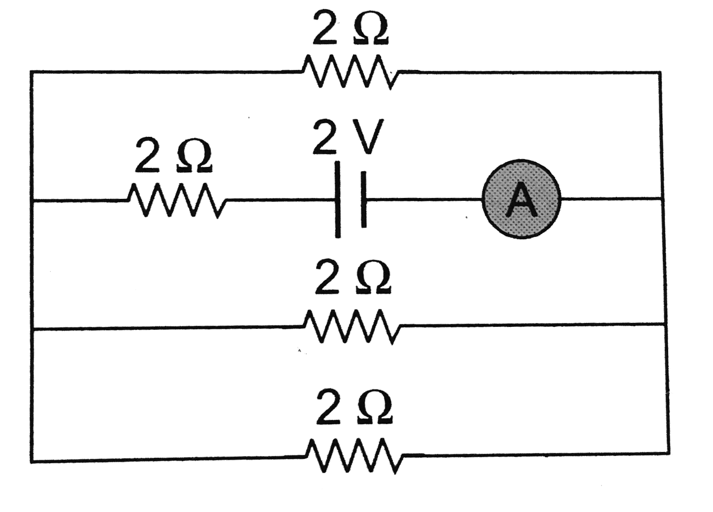
The reading of the ammeter as per figure shown is
 A18AB34AC12AD2A
The reading of the ammeter as per figure shown is

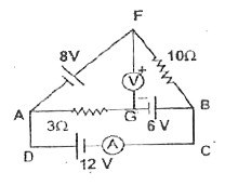
View SolutionFind the reading of ammeter A and voltmeter V shown in the figure assuming the instruments to be ideal

View SolutionFind the reading of ammeter A and voltmeter V shown in the figure assuming the instruments to be ideal

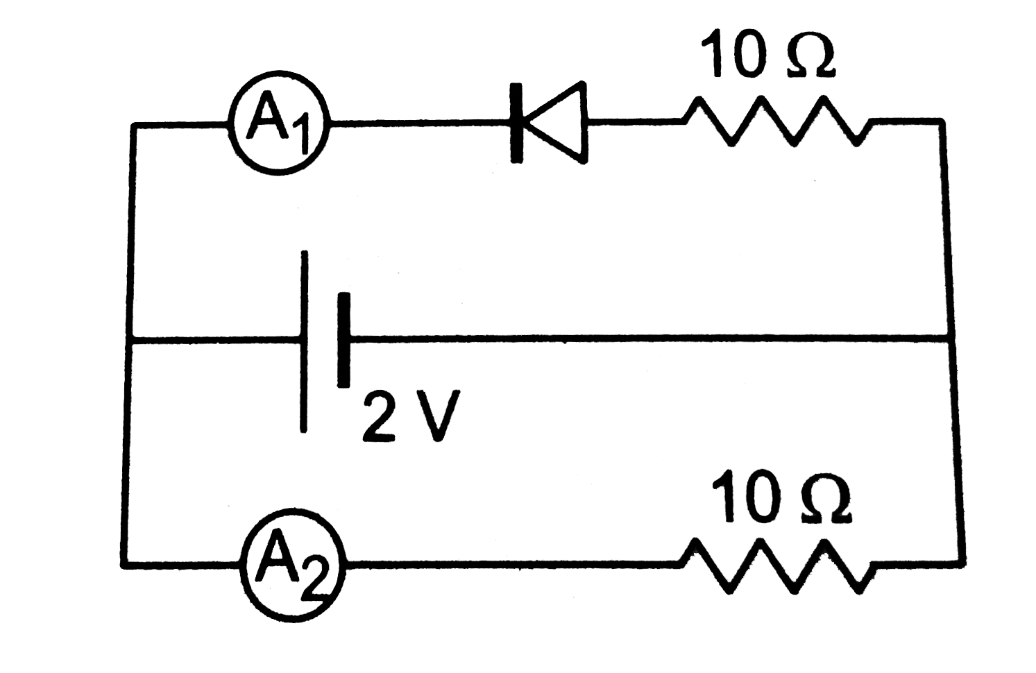
View SolutionWhat are the reading of ammeters A1 and A2 shown in Fig.? Neglect the resistances of the ammeters, when the p-n junction used is ideal one.

View SolutionThe reading of ammeter in the circuit shown in the figure is
_PHY_E05_104_Q01.png)
View SolutionThe reading of ammeter in the circuit shown in the figure is
_PHY_E05_104_Q01.png)
View SolutionThe reading of ammeter in the circuit shown in the figure is
_PHY_E05_032_Q01.png)
View Solution

