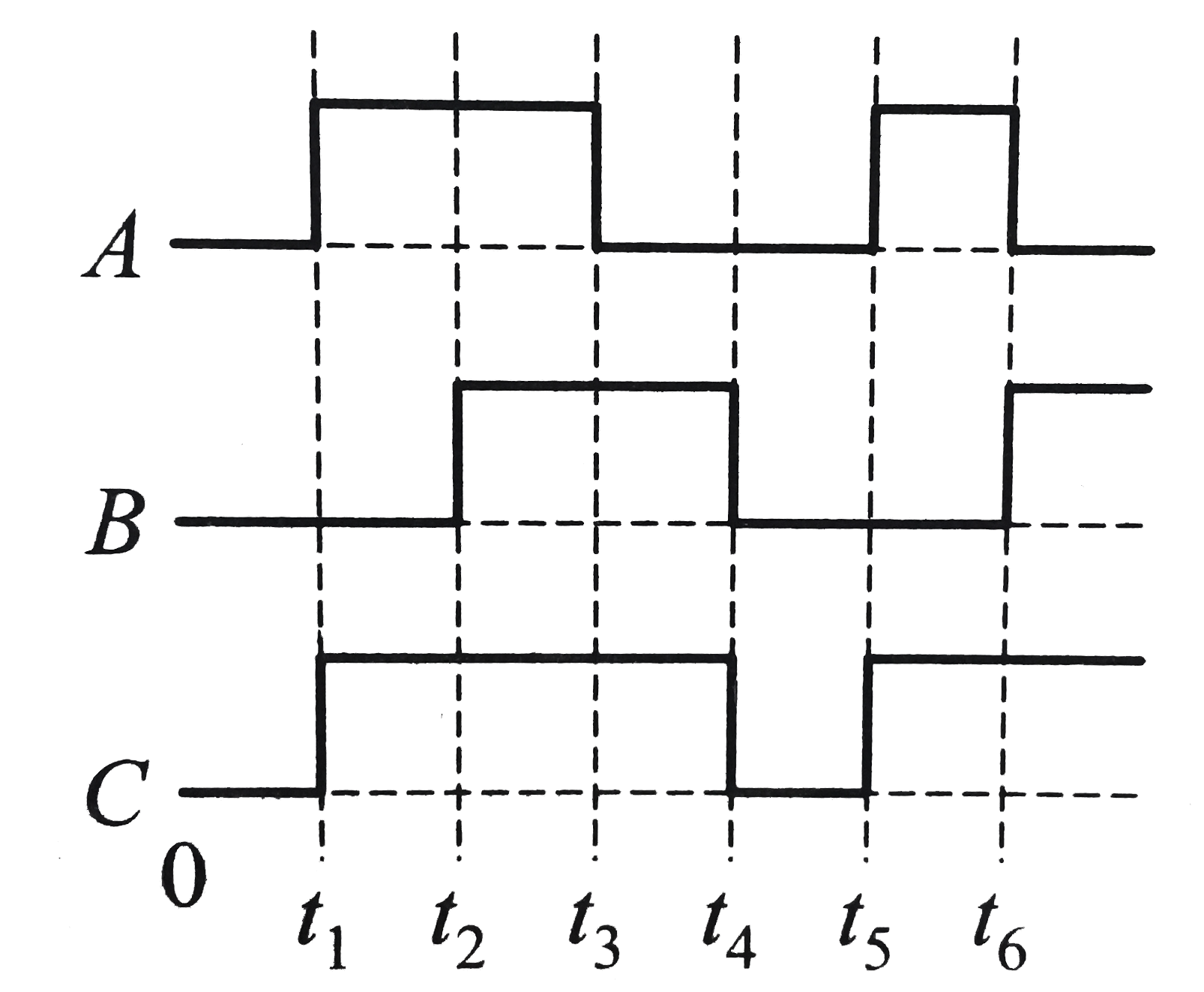
The figure shows a logic circuit with two inputs A and B and the output C. The voltage wave forms across A, B and Care as given. The logic gate circuit is:

OR gate
NOR gate
AND gate
NAND gate
The correct Answer is:A
Topper's Solved these Questions
- SEMICONDUCTOR ELECTRONICS : METERIALS, DEVICES AND SIMPLE CIRCUITSBOOK - DISHA PUBLICATIONCHAPTER - SEMICONDUCTOR ELECTRONICS : METERIALS, DEVICES AND SIMPLE CIRCUITSEXERCISE - EXERCISE -1: CONCEPT BUILDER (TOPICWISE)
56 Videos
- RAY OPTICS AND OPTICAL INSTRUMENTSBOOK - DISHA PUBLICATIONCHAPTER - RAY OPTICS AND OPTICAL INSTRUMENTSEXERCISE - Exercise -2 : Concept Applicator
26 Videos
- SYSTEM OF PARTICLES & ROTATIONAL MOTION BOOK - DISHA PUBLICATIONCHAPTER - SYSTEM OF PARTICLES & ROTATIONAL MOTION EXERCISE - EXERCISE-2 : CONCEPT APPLICATOR
28 Videos
Similar Questions
The figure shows a logic circuit with two inputs A and B and the output C. The voltage wave forms across A,B and C are as given. The logic circuit gate is
View SolutionThe following figure shows a logic gate circuit with two inputs A and B and the output C. The voltage waveforms of A, B and C are as given The logic circuit is:
View Solution
Knowledge Check
The figure shows a logic circuit with two inputs A and B and the output C. The voltage wave forms across A,B and C are as given. The logic circuit gate is
 AOR gateBNOR gateCAND gateDNAND gate
The figure shows a logic circuit with two inputs A and B and the output C. The voltage wave forms across A,B and C are as given. The logic circuit gate is
 ANAND gateBOR gateCNOR gateDAND gate
The following figure shows a logic gate circuit with two inputs A and B and the output Y. The voltage waveforms of A,B and the output Y are as given
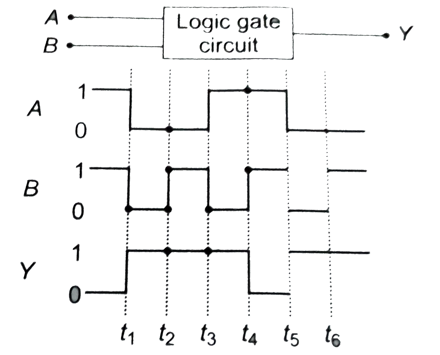 ANOR gateBOR gateCAND gateDNAND gate
The following figure shows a logic gate circuit with two inputs A and B and the output C. The voltage waveforms of A, B and C are as shown below.
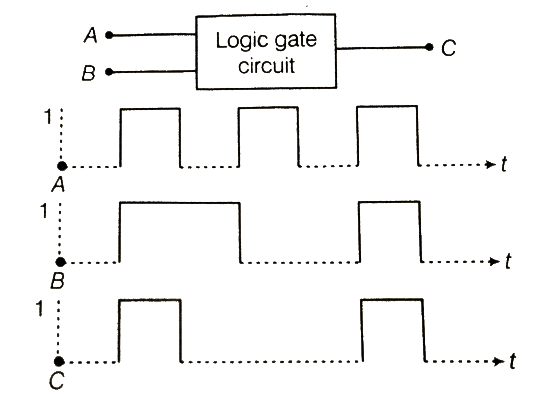
The logic circuit gate is
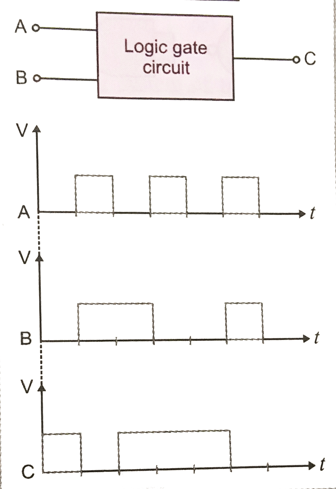
View SolutionFig, shows a logic gate circuit with two input A and B and the output C. The voltage wave form of A, B and C are as shown in Fig.The logic gate circuit is
View SolutionThe following figure shows a logic gate circuit with two inputs A and B and the output Y. The voltage waveforms of A,B and Y are as given :
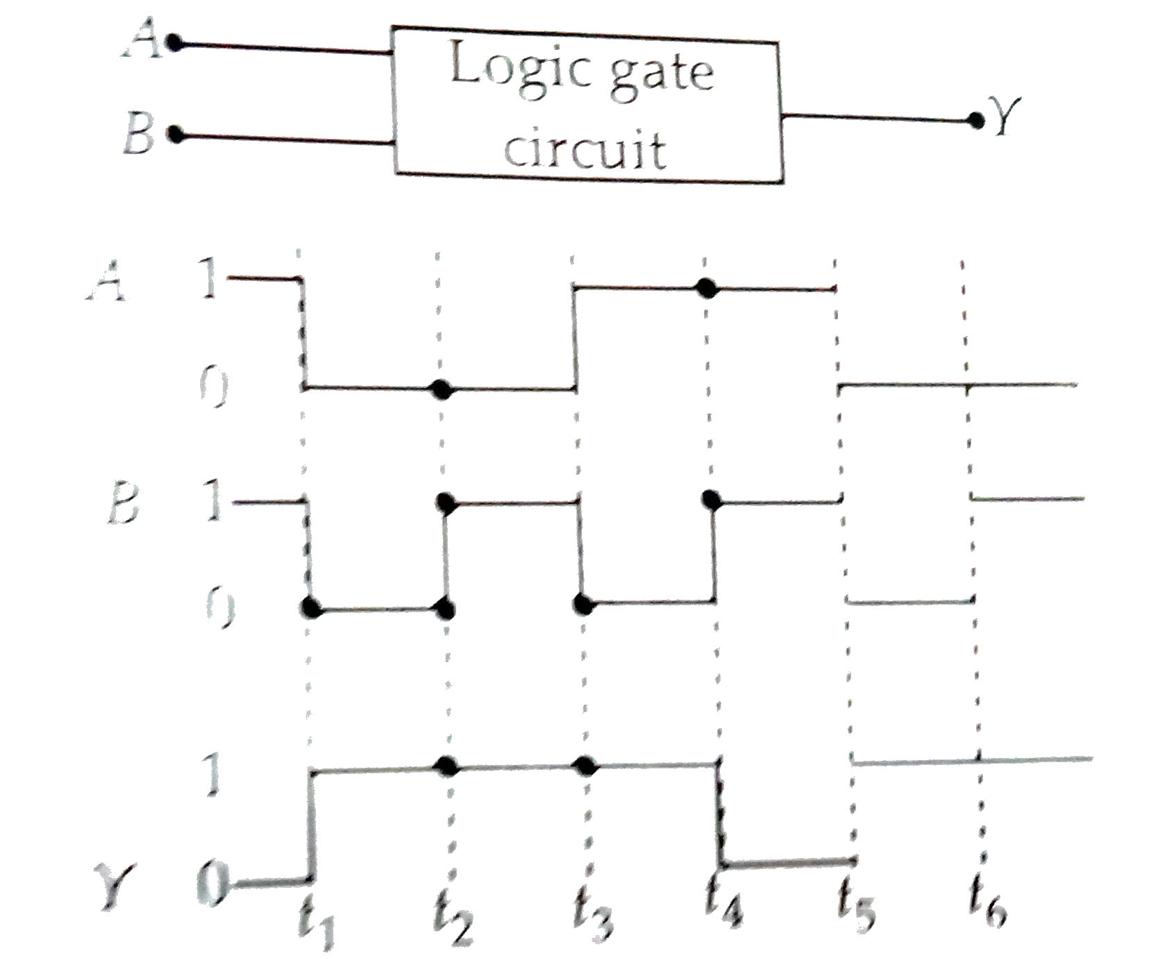
The logic gate is
View SolutionThe following figure shows a logic gate circuit with two inputs A and B and the output Y. The voltage waveforms of A,B and Y are as given :

The logic gate is
View SolutionThe following figure shows a logic gate circuit with two inputs A and B and the output C. The voltage waveforms of A, B and C are as shown below
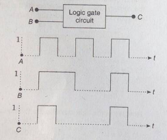
The logic circuit gate is
View Solution

