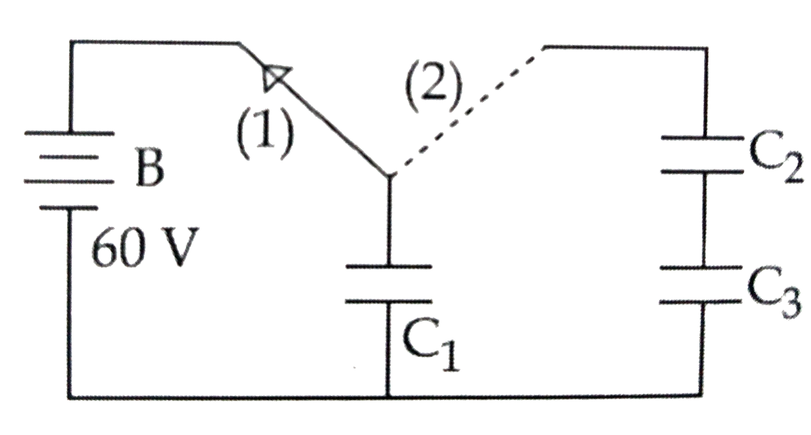
A capacitor C1=1.0μF F is charged up to a voltage V=60 V by connecting it to battery B through switch (1) Now C1 is disconnected from battery and connected to a circuit consisting of two uncharged capaictors C2=3.0μFandC3=6.0μF through switch (2) as shown in the figure The sum of final charges on C2andc3 is :
40μC
36μC
20μC
54μC
Step by step video & image solution for A capacitor C_(1) =1.0 muF F is charged up to a voltage V=60 V by connecting it to battery B through switch (1) Now C_(1) is disconnected from battery and connected to a circuit consisting of two uncharged capaictors C_(2)=3.0 mu F and C_(3)=6.0 mu F through switch (2) as shown in the figure The sum of final charges on C_(2) and c_(3) is : by Physics experts to help you in doubts & scoring excellent marks in Class 12 exams.
Updated on:21/07/2023Topper's Solved these Questions
Similar Questions
A capacitor of capacitance C1=1.0μF charged up to a voltage V=110V is connected in parallel to the teminals of a circuit consisting of two uncharged capacitors connected in series and possessing the capacitances Cs=2.0μF and Cs=3.0μF. What charge will flow through the connecting wires ?
View SolutionA capacitor of capacitance C1=1.0μF charged upto a voltage V=110V is connected in parallel to the terminals of a circuit consisting of two uncharged capacitors connected in series and possessing the capacitance C2=2.0μF and C3=3.0μF. What charge will flow through the connecting wires?
View Solution
Knowledge Check
Two capacitors C1 and C2 are charged to same potential V, but with opposite polarity as shown in the figure. The switches S1 and S2 are then closed
 APotential difference across two capacitors are same and is given by (C1−C2)VC1+C2BPotential difference across two capacitors are same and is given by (C1+C2C1−C2)VCRatio of final energy to initial energy of the system is given by (C1−C2)2(C1+C2)2DRatio of final energy to initial energy of the system is given by (C1)2(C1+C2)2
Capacitor C1 is connected to a battery and charged till the magnitude of the charge on each plate is q0. Then, the battery is disconnected and C1 is connected to two other uncharged capacitors C2andC3 as shown in figure. Final charges on the capacitors (q1,q2andq3) are related by .
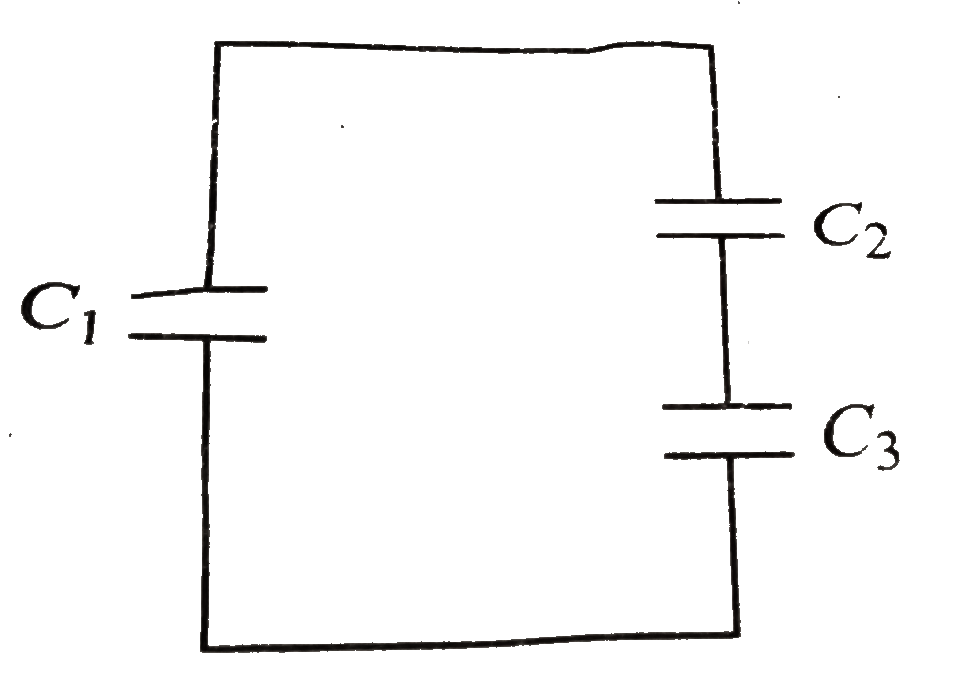 Aq0=q1+q2+q3Bq1+q2+q3=0Cq0=q3+q2,q1=0Dq0=q1+q2,q2=q3
A capacitor of capacity C1=1μF is charged to a potential of 100 V. The charging battery is then removed and it is connected to another capacitor of capacity C2=2μF. One plate of C2 is earthed as shown in figure. The charges on C1andC2 in steady state will be
 A50μC,50μCB100μC,zeroC1003μC,2003μCDzero,zer
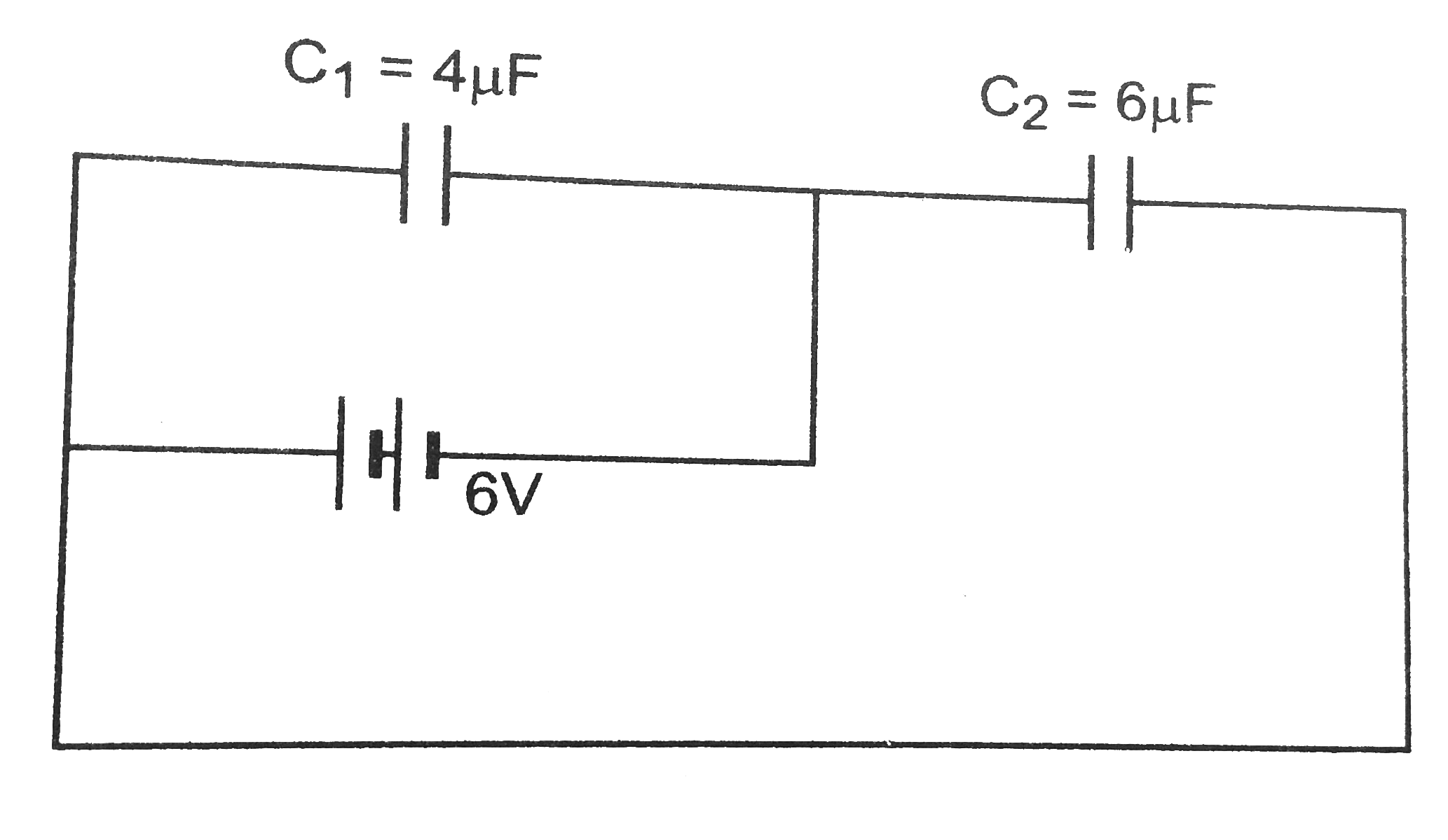
Two capacitors C1 and C2 are connected to a battery of 6V as shown in Fig. Find the charge on each capacitor.
View SolutionThree capacitors C1=2μF,C26μFandC3=12μFare connected as shown in figure. Find the ratio of the charges on capacitors C1,C2andC3 respectively :
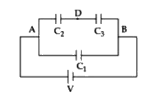
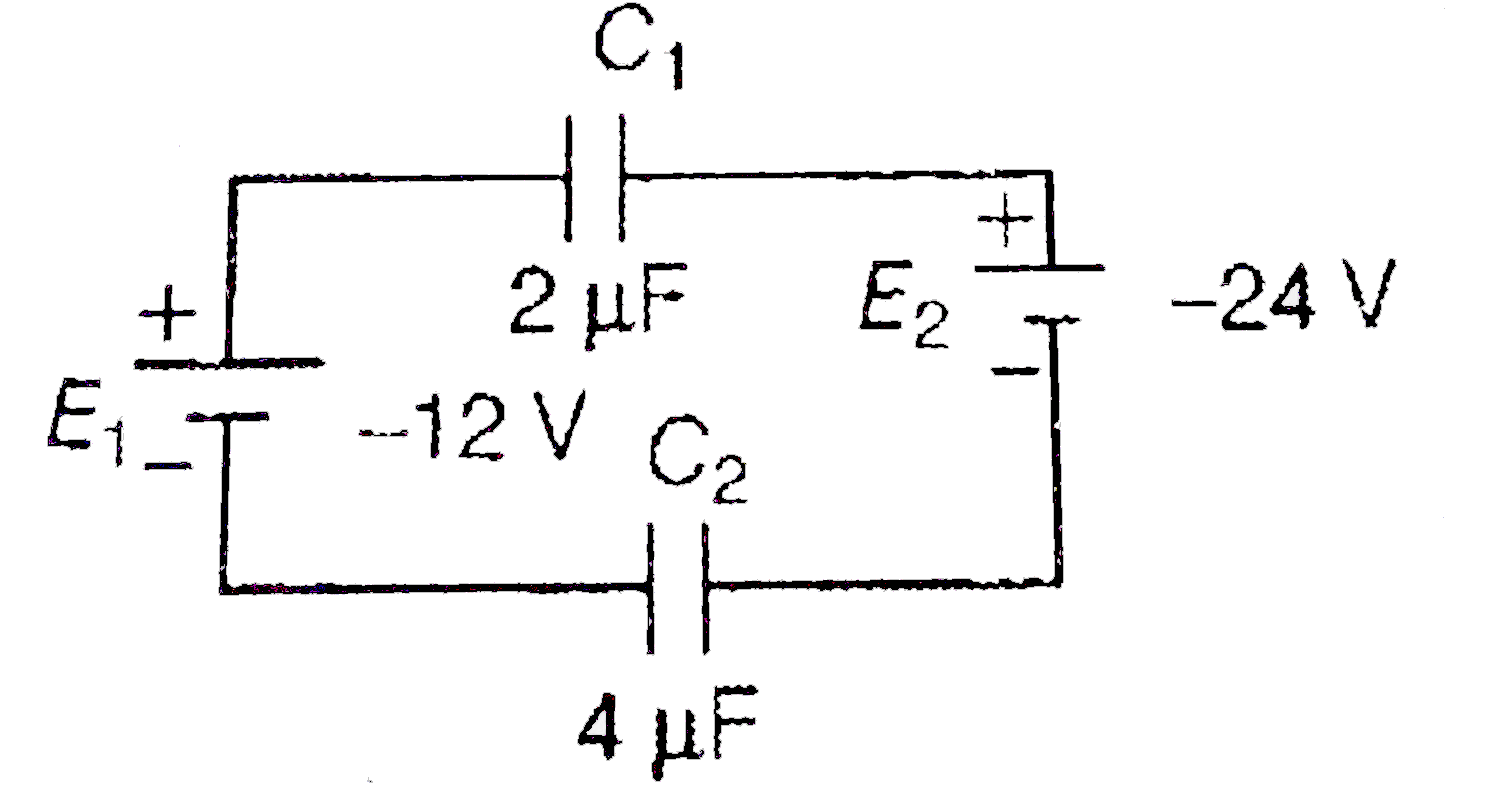
View SolutionTwo capacitors C1 and C2 are connected in a circuit as shown in figure. The potential difference (VA−VB) is
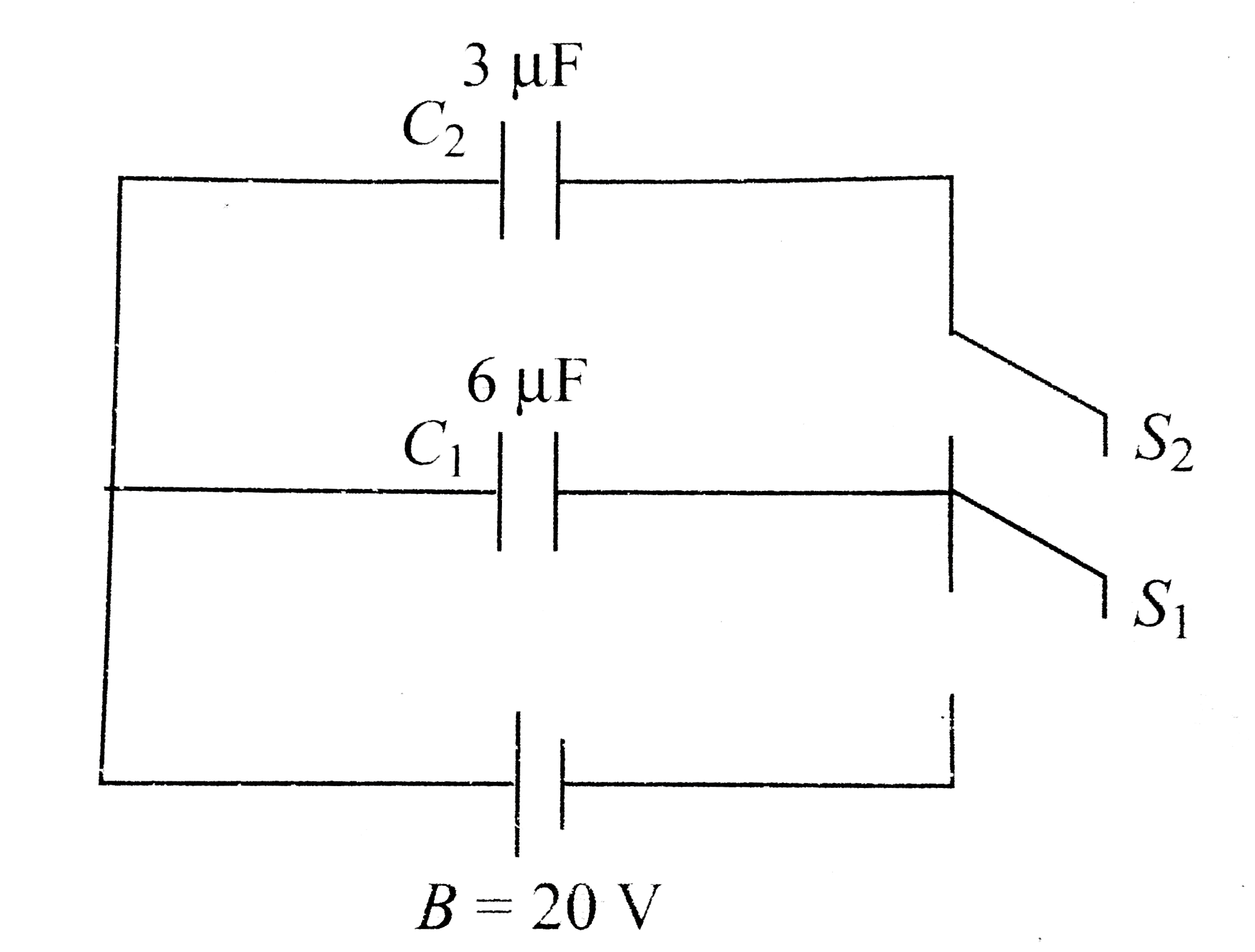
View SolutionIn the circuit shown in, C1=6μF,C2=3μF, and battery B=20V. The switch S1 is first closed. It is then opened, and S2 is closed. What is the final charge on C2
 .
.
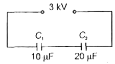
View SolutionCapacitors C1(10μF)andC2(20μF) are connected in series across a 3 kV supply, as shown. What is the charge on the capacitor C1 ?
View Solution
