Obtain the formula for the 'power loss' (i.e., power dissipated) in a conductor of resistance R, carrying a current I.

Consider a conductor with end points A and B in which a current I is flowing from A to B. Let electric potential at points A and B be V(A) and V(B) respectively. As current is flowing from A to B, obviously V(A) > V(B). Let V(A) – V(B) = V. In a time interval Δt, a charge Δq=I.Δt travels from A to B. Thus, potential energy of charge at A and B isU(A)=Δq.V(A) and U(B)=ΔqV(B) respectively.
∴ Change in potential energy ΔU=U(B)−U(A)=Δq[V(B)−V(A)]=−Δq.V=−lΔt.V
If charges were moving freely through the conductor under the action of an applied electric field then in accordance with law of conservation of energy, change in potential energy leads to a change in kinetic energy too such that,
ΔU=ΔK=0 or ΔK=−ΔU=I.VΔt
In practice, charge carriers in a conductor move with a steady drift velocity. This is because of their collisions with ions and atoms during transit. During collisions, the energy gained by the charges is shared with the atoms. The atoms vibrate more vigourously and the conductor heats up. Thus, in a conductor energy dissipated as heat during a time interval Δt is I.V.Δt. The energy dissipated per unit time is called the “power loss”. Thus,
Power loss P=IVΔtΔt=VI
As per Ohm.s law V =IR , hence
P=VI=V2R=I2R
Topper's Solved these Questions
- CURRENT ELECTRICITY BOOK - U-LIKE SERIESCHAPTER - CURRENT ELECTRICITY EXERCISE - LONG ANSWER QUESTIONS - I
47 Videos
- CURRENT ELECTRICITY BOOK - U-LIKE SERIESCHAPTER - CURRENT ELECTRICITY EXERCISE - LONG ANSWER QUESTIONS - II
8 Videos
- CURRENT ELECTRICITY BOOK - U-LIKE SERIESCHAPTER - CURRENT ELECTRICITY EXERCISE - VERY SHORT ANSWER QUESTIONS
39 Videos
- CBSE SAMPLE QUESTION PAPER 2019-20 (SOLVED)BOOK - U-LIKE SERIESCHAPTER - CBSE SAMPLE QUESTION PAPER 2019-20 (SOLVED)EXERCISE - SECTION D
6 Videos
- DUAL NATURE OF RADIATION AND MATTERBOOK - U-LIKE SERIESCHAPTER - DUAL NATURE OF RADIATION AND MATTEREXERCISE - SELF ASSESSMENT TEST SECTION-C (VERY SHORT ANSWER QUESTIONS)
3 Videos
Similar Questions
The average power dissipated in a pure inductor L carrying an alternating current of rms value I is .
View SolutionCurrent I flowing through resistor results in dissipation of power P. By what percentage will the power dissipated in the resistor increase if the current through the resistor is increased by 50%? Justify your answer with the help of mathematical calculations.
View Solution
Knowledge Check
The average power dissipated in a pure inductor L carrying an alternating current of rms value I is .
A12LI2BLI2C14LI2DzeroA power supply of fixed emf E is connected to a variable resistor (resistance = R) and an ammeter of resistance RA. The internal resistance of supply is r. The potential difference between the terminals of the power supply in closed circuits is denoted by V and current in circuit denoted by I. A graph is obtained between V and I by drawing varying amount of current from the supply. The correct V−I graph for the given situation is
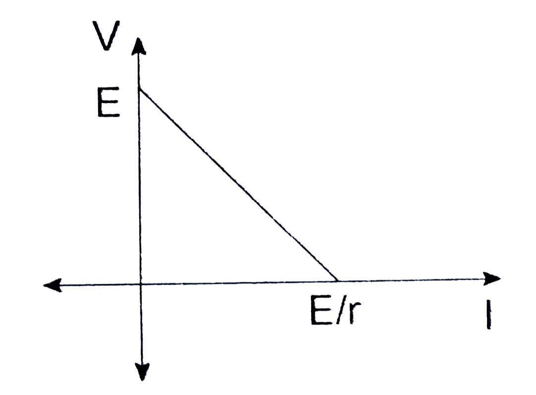
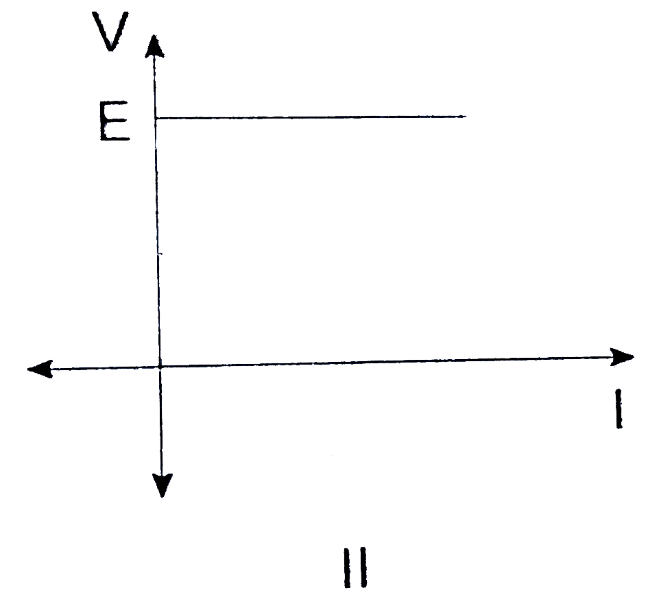

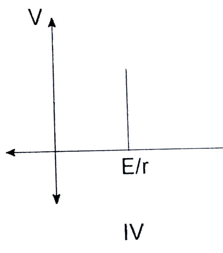 AGraph IBGraph IICGraph IIIDGraphIV
A coil and an inductance − free resistance R=25Ω are connected in parallel to the ac1 mains. Find the heat power generated in the coil provided a current I=0.90A is drawn from the mains. The coil and the resistance R carry currents I1=0.50A and I2=0.60A respectively.
View SolutionA voltage V=Vmsinωt is applied to a series L-C-R circuit. Derive the expression for the average power dissipated over a cycle. Under what condition (i) no power is dissipated even though the current flows through the circuit, (ii) maximum power is dissipated in the circuit ?
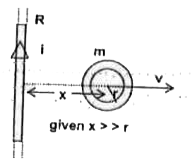
View SolutionA small conducting loop of radius r & resistance R is pulled with velocity v perpendicular to long straight current carrying conductor carrying a current i. If the power dissipated (P ) in the loop is constant find the variation of the velocity of the loop with the displacement x.
View SolutionA power supply of fixed emf E is connected to a variable resistor (resistance = R) and an ammeter of resistance RA. The internal resistance of supply is r. The potential difference between the terminals of the power supply in closed circuits is denoted by V and current in circuit denoted by I. A graph is obtained between V and I by drawing varying amount of current from the supply. The correct V−I graph for the given situation is


View SolutionIn the circuit shown ,the thermal power dissipated in R1 is P. The thermal power dissipated in R2 is .
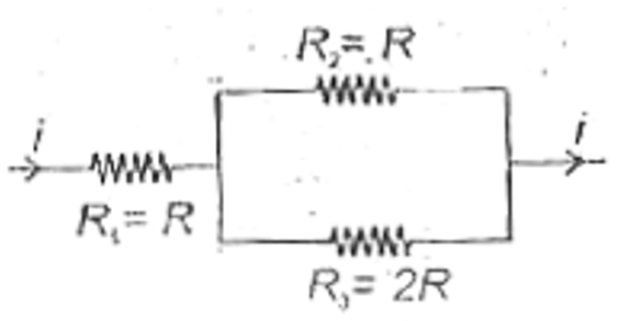
View SolutionIn the circuti shown ,the thermal power dissipated in R1 is P. The thermal power dissipated in R2 is .

View Solution
