Figure 27-11a shows a multiloop circuit containing one ideal battery and four resistances with the following values:
R1=20Ω,R2=20Ω,ε=12V,
R3=30Ω,R4=8.0Ω
(a) What is the current through the battery?
(b) What is the current i2 through R2?
(c) What is the current i3 through R3?
Noting that the current through the battery must also be the current through R1 we see that we might find the current by applying the loop rule to a loop that includes R1 because the current would be included in the potential difference across R1.
Incorrect method: Either the left-hand loop or the big loop should do. Noting that the emf arrow of the battery points upward, so the current the battery supplies is clockwisc, we might apply the loop rule to the left-hand loop, clockwise from point a. With i being the current through the battery, we would get
+ε−iR1−iR2−iR4=0
However, this equation is incorrect because it assumes that R1,R2,andR4, all have the same current i. Resistances R1andR4 do have the same current, because the current passing through R4 must pass through the battery and then through R1 with no change in value. However, that current splits at junction point b- only part passes through R2 the rest through R3.
Dead-end method: To distinguish the several currents in the circuit, we must label them individually as in Fig. 27-115. Then, circling clockwise from, we can write the loop rule for the teít-hand loop as
+ε±i1R1−i2R2−i1R4=0
Unfortunately, this equatinus contains two unknowns, i1andI2 we would need at least one more equation find them.
Sucessful method : A much easier option is to simplify the circuit of Fig 27011b by finding equivalent series and thus cannot be replaced with an equivalent resistance. However R2andR3 are not in series and thus cannot be replaced with an equivalent resistance. However R2andR3 are in parallel, so we can use either Eq 27-24 or Eq 27-25 to find their equivalent resistance R23. From the latter. R23=R2R3R2+R3=(20Ω)(30Ω)50Ω=12Ω
We can now redraw the circuit as in Fig. 27 11c, note that the current through R23 must be i1 because charge that moves through R1andR4 must also move through R23 For this simple one-loop circuit, the loop rule (applied clockwise from point a as in Fig. 27-11d) yields +ε−i1R1−i1R23−i1R4=0
Substituting the given data, we find
12V−i1(20Ω)−i1(12Ω−i1(8.0Ω)=0
which gives us i1=12V40Ω=0.30A
(b) (1) We must now work backward from the equivalent circuit of Fig. 27-11d, where R23 has replaced R2andR3 (2) Because R2andR3 are in parallel, they both have the same potential difference across them as R23.
Working backward: We know that the current through R23is(1)=0.30A. Thus, we can use Eq. 26-8 (R= V/i) and Fig. 27-11e to find the potential difference V23 across R23.
Setting R23=i1R23=(0.30A)(12Ω)=3.6V
The potential difference across R is thus also 3.6 V (Fig. 27-11f), so the current i2 in R2 must be, by Eq. 26-8 and Fig 27-11g.
i2=V2R2=3.6V20Ω=0.18A
(c) We can answer by using either of techniques : (1) Apply Fiq 26-8 as we just did. (2) Use the junction rule, which tells us that at point b in Fig. 27-11b the incoming current i1 and the outgoing currents, i2andi3 are related by i1=i2+i3
Calculation : Rearranging this junction-rule result yields the result displayed in Fig 27-11g:
i3=i1−i2=0.30A−0.18A
=0.12 A

Figure 27-11
(a) A circuit with an ideal battery. (b) Label the currents. (c) Replacing the parallel resistors with their equivalent (d)-(g) Working backward to find the currents through the paralel resistors.
Topper's Solved these Questions
- BOOK - RESNICK AND HALLIDAYCHAPTER - CIRCUITSEXERCISE - Checkpoints7videos
CIRCUITS
- BOOK - RESNICK AND HALLIDAYCHAPTER - CIRCUITSEXERCISE - Problems45videos
CIRCUITS
- BOOK - RESNICK AND HALLIDAYCHAPTER - CENTER OF MASS EXERCISE - Practice Questions (Integer )4videos
CENTER OF MASS
- BOOK - RESNICK AND HALLIDAYCHAPTER - CIRCULAR MOTIONEXERCISE - CHECK POINTS6videos
CIRCULAR MOTION
Similar Questions
In Fig. 27-43, the current in resistance 6 is i6=2.80A the resistances are R1=R2=R3=2.00Ω,R4=16.0Ω,R5=8.00ΩandR6=4.00Ω. Wat is the emf of the ideal battery?
 View Solution
The emf and resistances in the circuit of Fig 27-8a have the following values:
ε1=4.4V.ε2=2.1V,
r1=2.3Ω,r2=1.8Ω,R=5.5Ω
(a) What is the current I in the circuit?
(b) What is the potential difference between the terminals of battery 1 in Fig. 27 8a?View Solution
Knowledge Check
- Question 1 - Select One
The potential difference in volt across the resistance R3 in the circuit shown in figure, is (R1=15Ω,R2=15Ω,R3=30Ω,R4=35Ω)
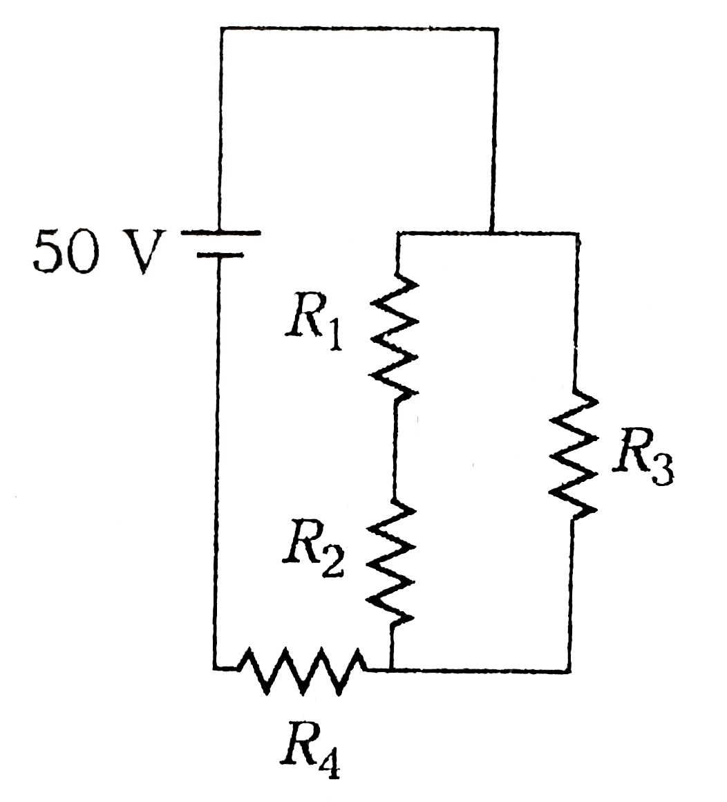 A5B7.5C15D12.5
 - Question 2 - Select One
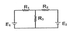
In the circuit shown below E1=4.0V,R1=2Ω,E2=6.0V,R2=4Ω and R3=2Ω. The current I1 is
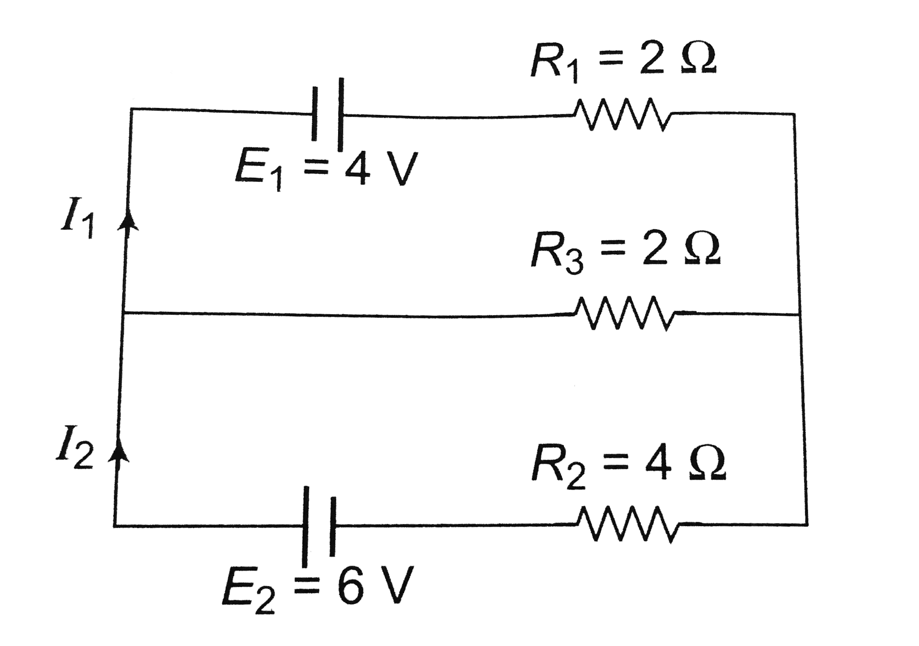 A1.6AB1.8AC1.25AD1.0A
 - Question 3 - Select One
In the R1=10Ω,R2=20Ω,R3=40ΩR4=80Ω and VA=5V,VB=10V,Vc=20V,VD=15V The current in the resistance R1 will be
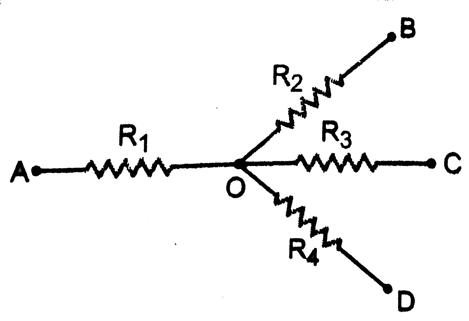 A0.4A toward OB0.4A away from OC0.8A toward OD0.8A toward O
In the following circuit ,E1=4V,R1=2Ω,
E2=6V,R2=2Oemga,andR3=4Ω. Find the currents i1andi2
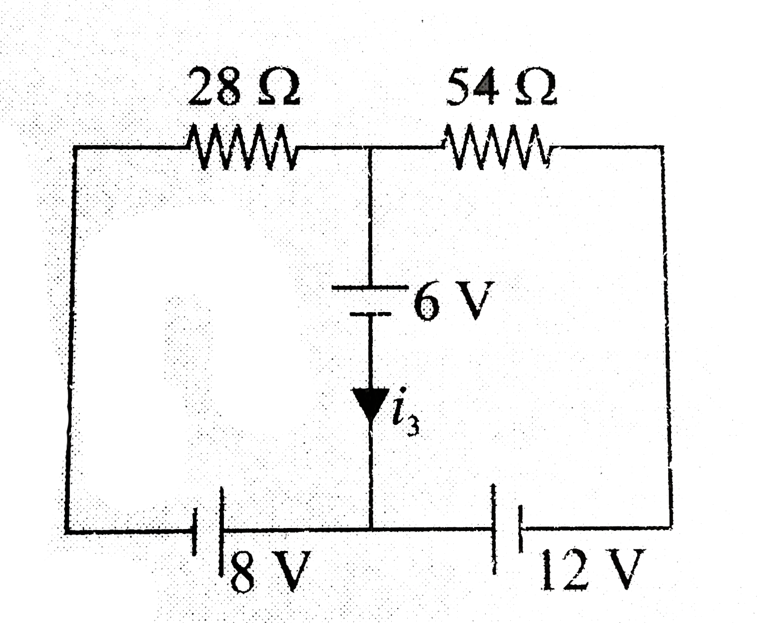 View Solution
If in the figure R1=10Ω,R2=40Ω,R3=30Ω,R4=20Ω,R5=60Ω and a 12 V battery is connected to the arrangement, calculate (i) the total resistance in the circuit and (ii) the total current flowing in the circuit.
View SolutionIf in Fig. 12.12, R1=10Ω,R2=40Ω,R3=30Ω,R5=60Ω, and a 12 V battery is connected to the arrangemtn. Calculate (a) the total resistance in the circuit, and (b) the total current flowing in the circuit.
View SolutionIn the diagram find out the current through 2Ω (R3) :
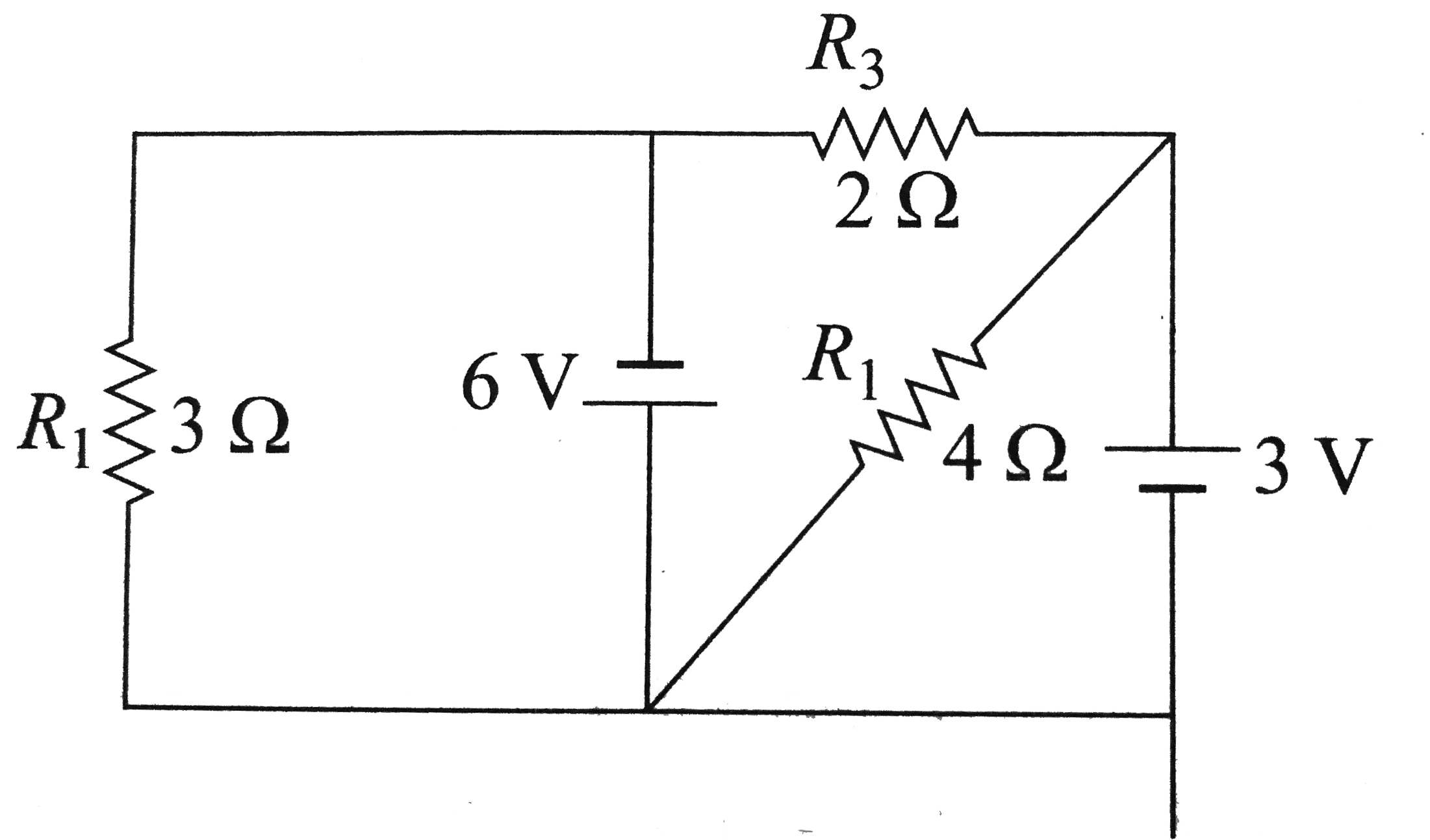 View Solution
In the circuit shown, E1=7V,E2=7V,R1=R2=1Ω and R3=3Ω respectively. The current through the resistance R3
 View Solution

