In Fig. 27-43, the current in resistance 6 is i6=2.80A the resistances are R1=R2=R3=2.00Ω,R4=16.0Ω,R5=8.00ΩandR6=4.00Ω. Wat is the emf of the ideal battery? 
The correct Answer is:96.6V
Step by step video, text & image solution for In Fig. 27-43, the current in resistance 6 is i_(6)= 2.80 A the resistances are R_(1)=R_(2)=R_(3)=2.00 Omega, R_(4)=16.0 Omega, R_(5)=8.00 Omega and R_(6)=4.00 Omega. Wat is the emf of the ideal battery? by Physics experts to help you in doubts & scoring excellent marks in Class 12 exams.
Updated on:21/07/2023Topper's Solved these Questions
- CIRCUITSBOOK - RESNICK AND HALLIDAYCHAPTER - CIRCUITSEXERCISE - Practice Questions (Single Correct Choice Type)
33 Videos
- CIRCUITSBOOK - RESNICK AND HALLIDAYCHAPTER - CIRCUITSEXERCISE - Practice Questions (More than One Correct Choice Type)
12 Videos
- CIRCUITSBOOK - RESNICK AND HALLIDAYCHAPTER - CIRCUITSEXERCISE - Checkpoints
7 Videos
- CENTER OF MASS BOOK - RESNICK AND HALLIDAYCHAPTER - CENTER OF MASS EXERCISE - Practice Questions (Integer )
4 Videos
- CIRCULAR MOTIONBOOK - RESNICK AND HALLIDAYCHAPTER - CIRCULAR MOTIONEXERCISE - CHECK POINTS
6 Videos
Similar Questions
Figure 27-11a shows a multiloop circuit containing one ideal battery and four resistances with the following values:
R1=20Ω,R2=20Ω,ε=12V,
R3=30Ω,R4=8.0Ω
(a) What is the current through the battery?
(b) What is the current i2 through R2?
(c) What is the current i3 through R3?
View SolutionFind the current flowing through the resistance R1 of the circuit shown in Fig. If the resistances are equal to R1=10Ω.R2=20Ω and R3=30Ω, and the potential of points 1,2 and 3 are equal to φ1=10V,φ2=6V, and φ3=5V

View Solution
Knowledge Check
In the circuit shown below E1=4.0V,R1=2Ω,E2=6.0V,R2=4Ω and R3=2Ω. The current I1 is
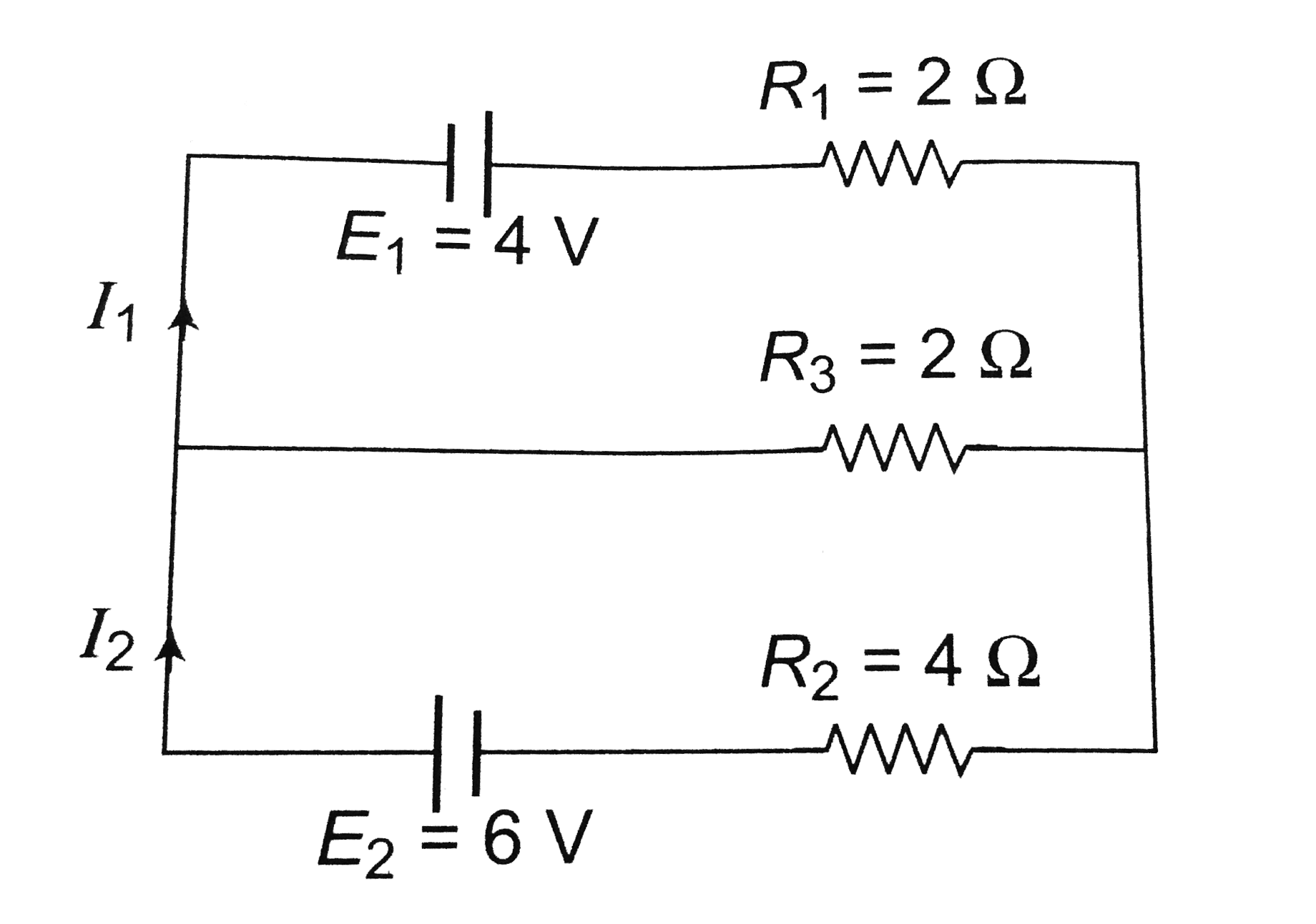 A1.6AB1.8AC1.25AD1.0A
The potential difference in volt across the resistance R3 in the circuit shown in figure, is (R1=15Ω,R2=15Ω,R3=30Ω,R4=35Ω)
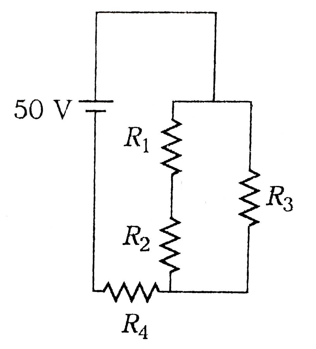 A5B7.5C15D12.5
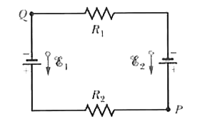
In Fig 27-56, the ideal batteries have emf emf12=200Vandε2=50V and the resistances are R1=3.0ΩandR2=2.0Ω. If the potential at P is 100 V, what is at at Q?
View SolutionA constant voltage V=25V is maintained between points A and B of the circuit (Fig). Find the magnitude and direaction of the current flowing through the segment CD if the resistances are equal to R1=1.0Ω,R2=2.0Ω,R3=3.0Ω adn R4=4.0Ω.

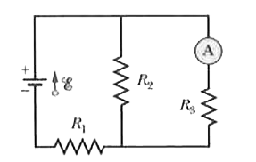
View SolutionIn Fig 27-59, what current does the ammeter read if ε=5.0V (ideal battery), R1=2.0Ω,R2=9.0ΩandR3=6.0Ω? (b) The ammeter and battery are now interchanged. Show that are ammeter reading is unchanged.
View SolutionIn the circuit shown in Fig, the sources have emf'sξ1=1.5V,ξ2=2.0V,ξ3=2.5V , and the resistances are equal to R1=10Ω,R2=20Ω,R3=30Ω. The internal resistances of the sources are negligible. Find : ltbrtgt (a) the current flowing thorugh teh resistance R1 ,
(b) a potential differences φA−φB between the points A and B between the points A and B.

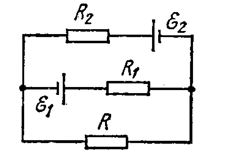
View SolutionFind the magnitude and direction of the current flowing through the resistance R in the circuit shown in Fig. if the emf's of the sources are equal to E1=1.5V and E2=3.7V and the resistances are equal to R1=10Ω,R2=20Ω,R=5.0Ω. The internal resistances of the sources are neglible.
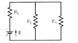
View SolutionIn Fig. 27-42, the resistances are R1=3.00Ω,R2=700Ω. and the battery is ideal. What value of R3 maximizes the dissipation rate in resistance 3?
View Solution
