For the circuit shown in the following figure, the 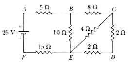
Potential difference between points B and E is 5 V
Potential difference between points A and B is 10 V
Current in the 4Ω resistor is 0.25A
Current in the 4Ω resistor is 0.5 A
The correct Answer is:A, D
Step by step video, text & image solution for For the circuit shown in the following figure, the by Physics experts to help you in doubts & scoring excellent marks in Class 12 exams.
Updated on:21/07/2023Topper's Solved these Questions
- CIRCUITSBOOK - RESNICK AND HALLIDAYCHAPTER - CIRCUITSEXERCISE - Practice Questions (Linked Comprehension)
11 Videos
- CIRCUITSBOOK - RESNICK AND HALLIDAYCHAPTER - CIRCUITSEXERCISE - Practice Questions (Matrix Match)
4 Videos
- CIRCUITSBOOK - RESNICK AND HALLIDAYCHAPTER - CIRCUITSEXERCISE - Practice Questions (Single Correct Choice Type)
33 Videos
- CENTER OF MASS BOOK - RESNICK AND HALLIDAYCHAPTER - CENTER OF MASS EXERCISE - Practice Questions (Integer )
4 Videos
- CIRCULAR MOTIONBOOK - RESNICK AND HALLIDAYCHAPTER - CIRCULAR MOTIONEXERCISE - CHECK POINTS
6 Videos
Similar Questions
Knowledge Check
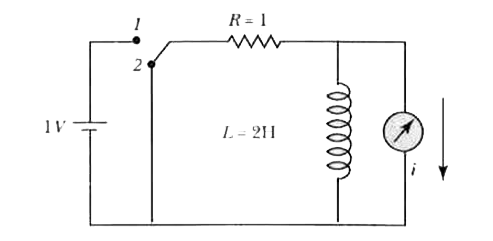
In the circuit shown in the following figure, the switch is moved to position 1 at t = 0. Which of the following most closely represents the current I as a function of time?
 A
A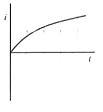 B
B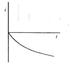 C
C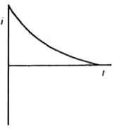 D
D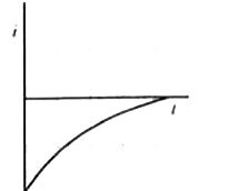
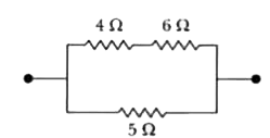
In the circuit shown in the following figure, the heat product in the 5Ω resistance due to the current flowing it is 10 cal/s. The heat generated in 4Ω resistance and 6Ω resistor is
 A1 cal/sB2 cal/sC3 cal/sD4 cal/s
When the switch is closed in the circuit as shown in the following figure, the light bulb become bright in an inperceptibly short-time interval, and then gradually goes out. We interpret this to mean that
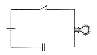 AElectrons on the negative terminal of the battery reach a capacitor plate almost instantaneouslyBElectrons from a capacitor plate travel to the positive terminal of the battery almost instantaneouslyCThe capacitor must already have had charge on its platesDThe battery establishes an electric field in the circuit almost instantaneously
In the circuit shown in the following figure, find
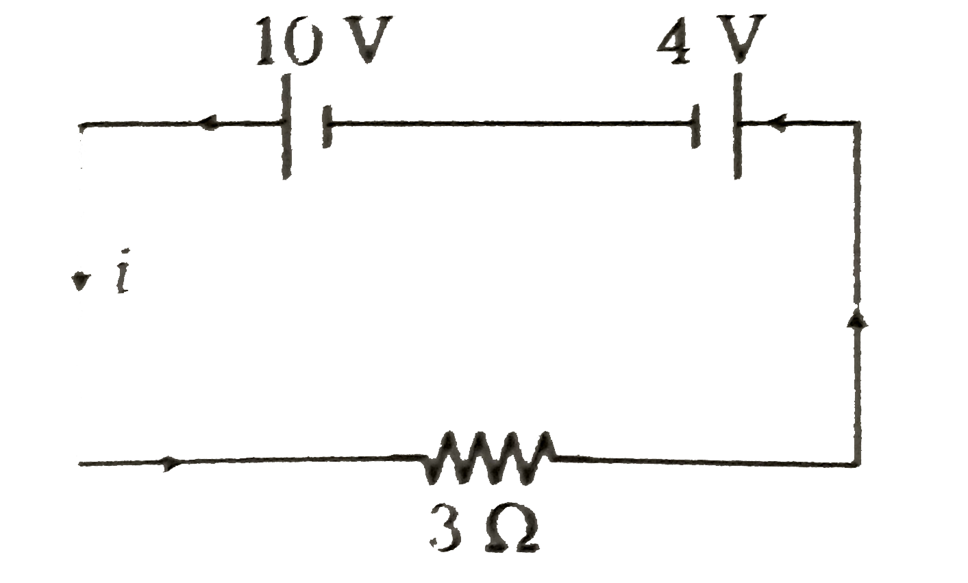
View SolutionFor the circuit shown in the figure
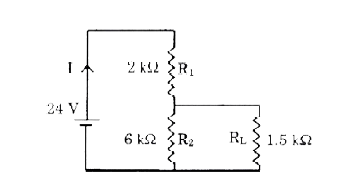
View SolutionIf voltage V is applied across terminals a and b of the circuit shown in the following figure, which of the statements below is true? (Notation: i4 is current through 4.00Ω resistor,...)
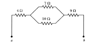
View SolutionConsider the circuit shown in the following figure.
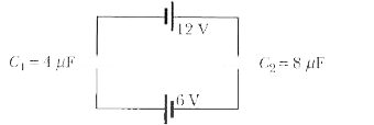
View SolutionIn the circuit shown in the following figure some potential difference is applied between A and B . IF C is joined to D,
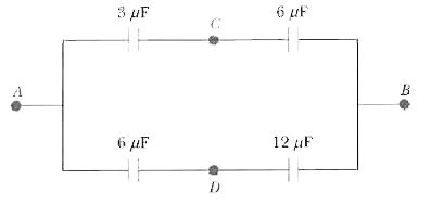
View Solution

