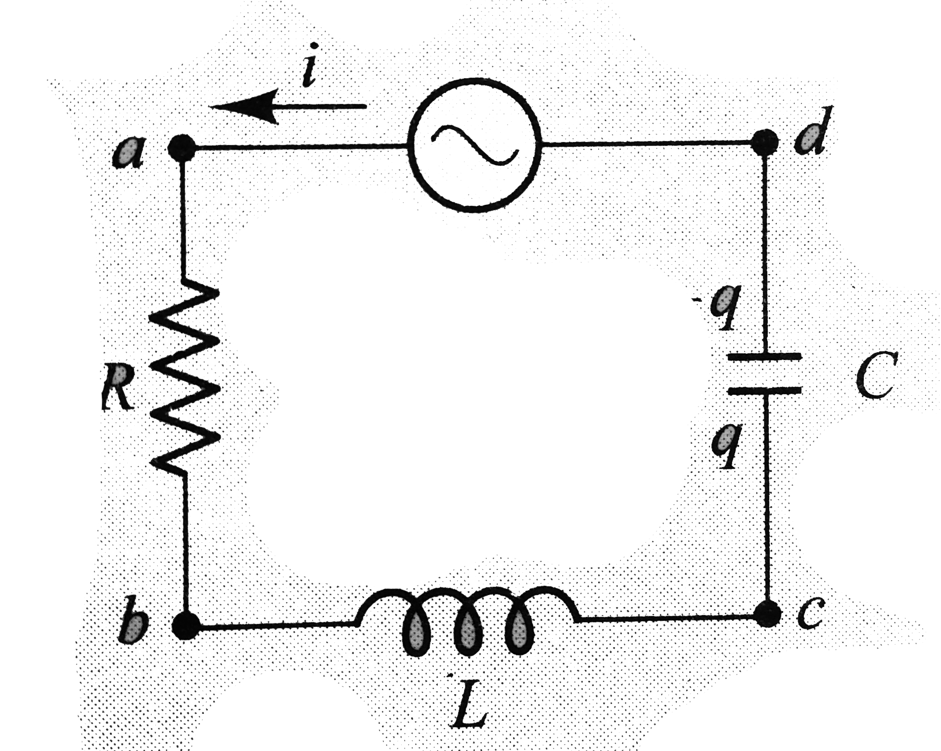
Let R=200 Ω, C= 15.0 μF, L=230 mH , fd = 60.0 Hz, and Em=36.0 V . (These parameters are those used in the earlier sample problems).
(a) What is the current amplitude I ?
To find the current amplitude I in an RLC circuit, we can follow these steps:
Step 1: Identify the given values
We have the following parameters:
- Resistance R=200Ω
- Capacitance C=15.0μF=15.0×10⁻⁶F
- Inductance L=230mH=230×10−3H
- Frequency fd=60.0Hz
- Maximum EMF Em=36.0V
Step 2: Calculate the angular frequency ω
The angular frequency ω is given by the formula:
ω=2πfd
Substituting the frequency:
ω=2π×60.0Hz=120πrad/s
Step 3: Calculate the reactance of the capacitor XC
The capacitive reactance XC is given by:
XC=1ωC
Substituting the values:
XC=1120π×15.0×10−6≈177Ω
Step 4: Calculate the reactance of the inductor XL
The inductive reactance XL is given by:
XL=ωL
Substituting the values:
XL=120π×230×10−3≈87Ω
Step 5: Calculate the total impedance Z
The total impedance Z in an RLC circuit is given by:
Z=√R2+(XL−XC)2
Substituting the values:
Z=√2002+(87−177)2=√2002+(−90)2
Calculating:
Z=√40000+8100=√48100≈219.3Ω
Step 6: Calculate the current amplitude I
The current amplitude I can be calculated using Ohm's law:
I=EmZ
Substituting the values:
I=36.0V219.3Ω≈0.164A
Final Answer
The current amplitude I is approximately 0.164A.
---
We have the following parameters:
- Resistance R=200Ω
- Capacitance C=15.0μF=15.0×10⁻⁶F
- Inductance L=230mH=230×10−3H
- Frequency fd=60.0Hz
- Maximum EMF Em=36.0V
The angular frequency ω is given by the formula:
ω=2πfd
Substituting the frequency:
ω=2π×60.0Hz=120πrad/s
The capacitive reactance XC is given by:
XC=1ωC
Substituting the values:
XC=1120π×15.0×10−6≈177Ω
The inductive reactance XL is given by:
XL=ωL
Substituting the values:
XL=120π×230×10−3≈87Ω
The total impedance Z in an RLC circuit is given by:
Z=√R2+(XL−XC)2
Substituting the values:
Z=√2002+(87−177)2=√2002+(−90)2
Calculating:
Z=√40000+8100=√48100≈219.3Ω
The current amplitude I can be calculated using Ohm's law:
I=EmZ
Substituting the values:
I=36.0V219.3Ω≈0.164A
The current amplitude I is approximately 0.164A.
Topper's Solved these Questions
- ELECTROMAGNETIC OSCILLATIONS AND ALTERNATING CURRENT BOOK - RESNICK AND HALLIDAYCHAPTER - ELECTROMAGNETIC OSCILLATIONS AND ALTERNATING CURRENT EXERCISE - Check Point
8 Videos
- ELECTROMAGNETIC OSCILLATIONS AND ALTERNATING CURRENT BOOK - RESNICK AND HALLIDAYCHAPTER - ELECTROMAGNETIC OSCILLATIONS AND ALTERNATING CURRENT EXERCISE - Problems
30 Videos
- ELECTROMAGNETIC INDUCTIONBOOK - RESNICK AND HALLIDAYCHAPTER - ELECTROMAGNETIC INDUCTIONEXERCISE - PRACTICE QUESTIONS (Integer Type)
14 Videos
- ELECTROMAGNETIC WAVES BOOK - RESNICK AND HALLIDAYCHAPTER - ELECTROMAGNETIC WAVES EXERCISE - PRACTICE QUESTIONS (Integer Type)
3 Videos
Similar Questions
In Fig. R = 25.0 Ω, C = 4.70 μF, and L = 25.0 mH. The generator provides an emf with rms voltage 75.0 V and frequency 550 Hz. (a) What is the rms current? What is the rms voltage across (b) R, (c) C, (d) L, (e) C and L together, and (f) R, C, and L together? At what average rate is energy dissipated by (g) R, (h) C, and (i) L?
View Solution(a) In a series L-C-R circuit with an AC source, R =300Ω, C = 20μF,L=1.0H,V0=50√2Vandf=50πHz. Find (i) the rms current in the circuit and (ii) the rms voltage across each element.
(b) Consider the situatiuon of the previous part. find the average electric field energy stored in the capacitor and the average magnetic field energy stored iun the coil .
View Solution
Knowledge Check
A series R−L−C circuit has R=100Ohm.L=0.2mH and C=12μF. The applied voltage V=20sinωt.
When the current lags the applied voltage by 45∘, the equation of the current isA0.2sin(ωt+tan−10.3)B0.2sin(ωt−tan−10.3)C0.3sin(ωt+tan−10.3)D0.3sin(ωt−tan−10.3)In a series A.C. circuit , R=100Ω, XL=300Ω and XC=200Ω. The phase difference between the applied e.m.f. and the current will be
A0B37∘C45∘D90∘
In the series curcuit of fig, suppose R=300Ω,L=60mH,C=0.50(μ)F, source amplitude is E0=50Vandω=10000rads−1. Find the reactances XLandXC, the impedance Z, the current amplitude I0, the phase angle ϕ, and the voltage amplitude across each circuit element.
 .
.
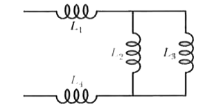
View SolutionThe inductor arrangement of Fig. 30-53, with L1 = 50.0 mH, L2 = 80.0 mH, L3 = 20.0 mH, and L4 = 15.0 mH, is to be connected to a varying current source. What is the equivalent inductance of the arrangement?

View SolutionCapacitance C is 15.0 μF and the sinusoidal alternating emf device operates at amplitude Em = 36.0 V and frequency fd= 60.0 Hz.
(a) What are the potential difference VC(t) across the capacitance and the amplitude VC of Vc(t) ? (b) What are the current IC(t) in the circuit as a function of time and the amplitude IC of Ic(t) ?
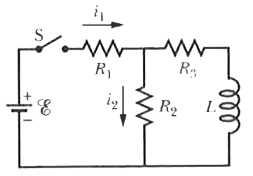
View SolutionIn Fig. 30-41, E = 100 V, R1=10.0Ω,R2=20.0Ω,R3=31.0Ω , and L = 2.00 H. Immediately after switch S is closed, what are (a) i1 and (b) i2? (Let currents in the indicated directions have positive values and currents in the opposite directions have negative values.) A long time later, what are (c) i1 and (d) i2? The switch is then reopened. Just then, what are (e) i1 and (f) i2? A long time later, what are (g) i1 and (h) i2?

View SolutionIn an L−C−R ereis circuit R=150Ω,L=0.0750H and C=0.0180μF . The source has voltage amplitude V=150V and a frequencey equal to the resonacne frequency of the circuit.
(a) What is the power factor ?
(b) What is the average power delivered by the source?
(c) The capacitor is replaced by one with C=0.0360μF and the source frequency is adjusted to the new resonance value. Then, what is the average power delivered by the source?
View SolutionResistance R is 200 Ω and the sinusoidal alternating emf device operates at amplitude Em=36.0 V and frequency fd=60.0 Hz.
(a) What is the potential difference vR(t) across the resistance as a function of time t, and what is the amplitude VR of VR(t) ? (b)What is the current vR(t) in the resistance and the amplitude IR of IR(t) ?
View Solution
