The inductor arrangement of Fig. 30-53, with L1 = 50.0 mH, L2 = 80.0 mH, L3 = 20.0 mH, and L4 = 15.0 mH, is to be connected to a varying current source. What is the equivalent inductance of the arrangement?
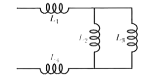
81.0 mH
Topper's Solved these Questions
- ELECTROMAGNETIC INDUCTIONBOOK - RESNICK AND HALLIDAYCHAPTER - ELECTROMAGNETIC INDUCTIONEXERCISE - PRACTICE QUESTIONS (Single Correct Choice Type)
45 Videos
- ELECTROMAGNETIC INDUCTIONBOOK - RESNICK AND HALLIDAYCHAPTER - ELECTROMAGNETIC INDUCTIONEXERCISE - PRACTICE QUESTIONS (More than One Correct Choice Type)
13 Videos
- ELECTROMAGNETIC INDUCTIONBOOK - RESNICK AND HALLIDAYCHAPTER - ELECTROMAGNETIC INDUCTIONEXERCISE - CHECKPOINTS
9 Videos
- ELECTRIC POTENTIALBOOK - RESNICK AND HALLIDAYCHAPTER - ELECTRIC POTENTIALEXERCISE - (PRACTICE QUESTIONS) Integer Type
1 Videos
- ELECTROMAGNETIC OSCILLATIONS AND ALTERNATING CURRENT BOOK - RESNICK AND HALLIDAYCHAPTER - ELECTROMAGNETIC OSCILLATIONS AND ALTERNATING CURRENT EXERCISE - Practice Questions (Integer)
7 Videos
Similar Questions
A coil of inductance L=300mH and resitance R=140mΩ is connected to a constant voltage source. How soon will the coil current reach η=50% of the steady-state value ?
View SolutionAn inductor (L=2000mH) is connected to an AC source of peak current. What is the instantaneous voltage of the source when the current is at its peak value?
View Solution
Knowledge Check
An inductor of 30 mH is connected to a 220 V, 100 Hz ac source. The inductive reactance is
A10.58ΩB12.64ΩC18.85ΩD22.67ΩIf L=25mH,C=1mF and R=10Ω then R.M.S current across source is
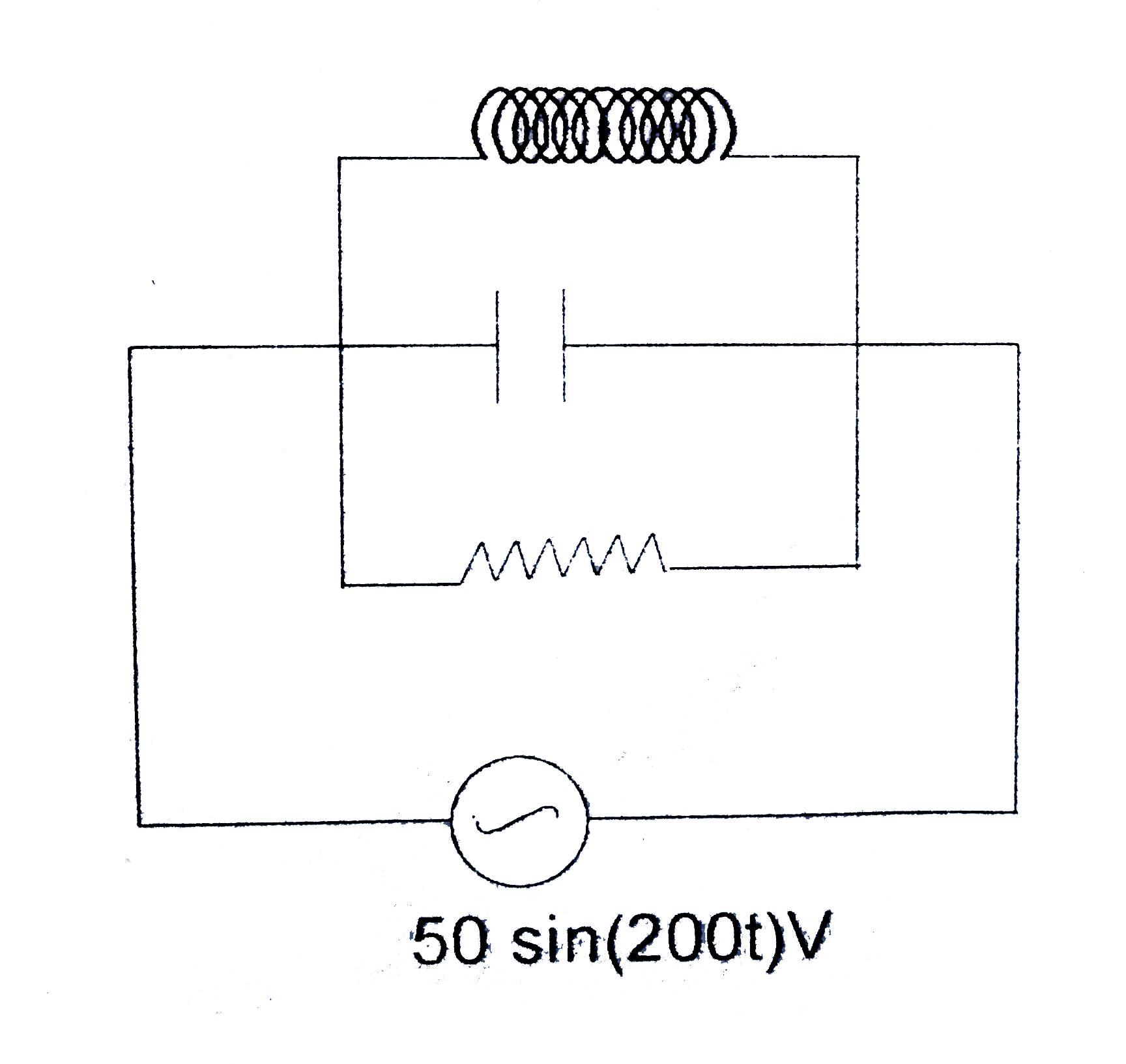 A5√2AB2.5√2AC12.5√2AD25√2A
Energy required to establish a current of 4 A in a coil of self-inductance L=200 mH is
A0.16 JB0.18 JC0.40 JD1.6 J
Let R=200 Ω, C= 15.0 μF, L=230 mH , fd = 60.0 Hz, and Em=36.0 V . (These parameters are those used in the earlier sample problems).
(a) What is the current amplitude I ?
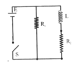
View SolutionAn inductor of inductance L = 400 mH and resistors of resistance R1=2Ω and R2=2Ω are connected to a battery of emf 12 V as shown in the figure. The internal resistance of the battery is negligible. The switch S is closed at t=0. The potential drop across L as a function of time is
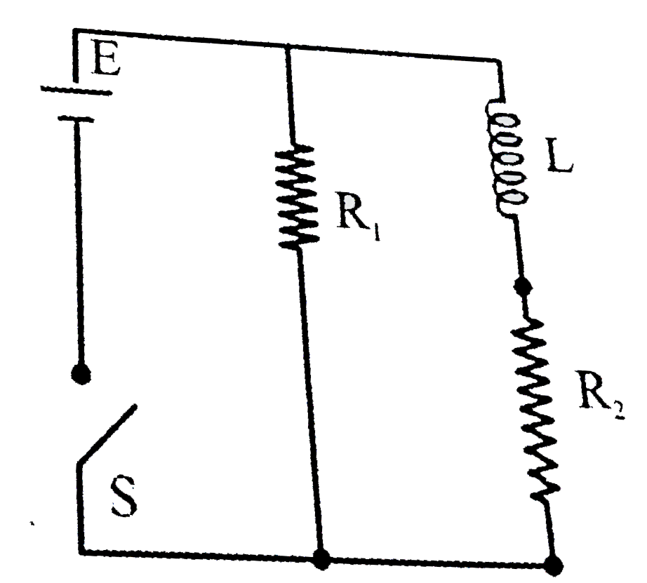
View SolutionAn inductor of inductance L = 400 mH and resistors of resistance R1=2Ω and R2=2Ω are connected to a battery of emf 12V as shown in the figure.The internal resistance of the battery is negligible.The switch S is closed at t = 0.The potential drop across L as a function of time is
View SolutionA 1.5 mH inductor in an LC circuit stores a maximum energy of 30μJ. What is the maximum current in the circuit ?
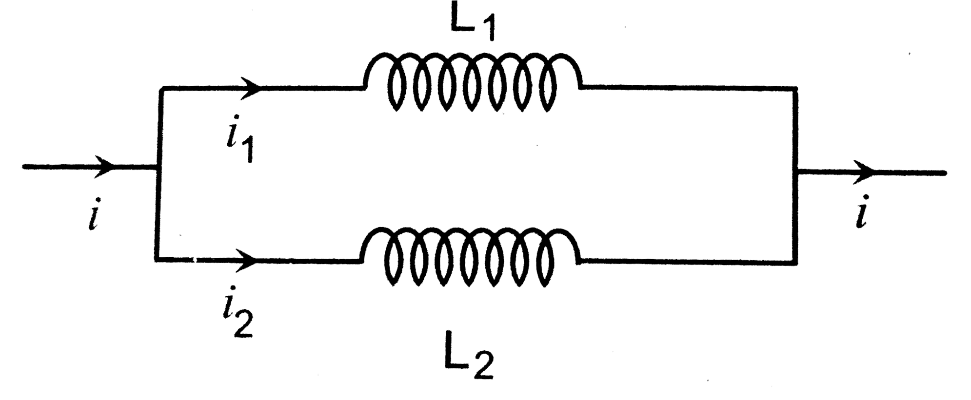
View SolutionTwo inductors L1 and L2 are connected in parallel and a time varying current flows as shown.
the ratio of current i1/i2
View Solution
